LAND ROVER ACCESSORY FITTING INSTRUCTIONS

VEHICLE :
PART NO :
KEYWORD :

LAND ROVER

RANGE ROVER VELAR

TOW BAR - DEPLOYABLE

VPLYT0334 - VPLYT0335 / VPLYT0341 / VPLKT0318 / VPLET0340 / VPLYT0338 / LR133263

FITTING INSTRUCTION

WARNING
  • Accessories which are not correctly installed can be dangerous. Read the instructions carefully prior to ordering and installation to make sure this accessory is applicable to your variant of vehicle. Comply with instructions at all times. If in doubt, contact your nearest approved retailer.
Accessory Kits Required Part Number
Electrically Deployable Towbar (Coil or Air suspension) VPLYT0334 (Coil) or VPLYT0335 (Air)
Electrically Deployable Towing Harness VPLYT0341
Towbar Control Module (TBM) VPLKT0318
TBM Foam Mounting Block VPLYT0338
Running Board Control Module (RBM) Foam Mounting Block VPLYT0340
Rear Bumper Towing Valance LR133263

Deployable Towbar (Bill Of Materials)

NOTE
  • For motor vehicle data see sheet at the end of these instructions.
  • Item (A) VPLYT0338 will 'NOT' need to be ordered if you already have deployable side steps installed to your vehicle.
  • Item (L) VPLYT0340 will 'ONLY' need to be ordered if you already have deployable side steps installed to your vehicle.
Parts List Quantity
(A) TBM Foam Mounting Block x1
(A1) TBM Foam Mounting Block fixing x2
(B) TBM x1
(C) Towing Harness x1
(C1) Cable Tie x10
(C2) Large Fuse x1
(C3) Small Fuse x2
(C4) Relay x1
(D) Link Cable x1
(E) Towbar Bracket - LH x1
(E1) Towbar Bracket Fixing x8
(F) Towbar Bracket - RH x1
(G) Deployable Towbar x1
(G1) Deployable Towbar Fixing x8
(H) Towing Valance Cover x1
(H2) Towing Valance Cover Fixing x2
(I) Switch Bezel x1
(J) Deployable Towbar Switch x1
(K) RBM Foam Mounting Block x1
Fitting Instruction
CAUTION
  • Under no circumstances is the motor to be removed from the towbar armature when being replaced. The complete armature assembly needs to be returned otherwise any claim will be rejected.
NOTE
  • Appearance of some illustrations will vary depending on the vehicle specification, but the essential information is always correct.
1

Place the vehicle on a 4 pillar ramp before installation of the towbar. Make sure to do this first as the startup battery will be disconnected later on in these instructions, making moving of the vehicle difficult.

2

Open the tailgate and fold down the second row seats (Refer to Owner's Handbook if unsure how to do this). Then remove parts in this order.

  1. Remove the parcel shelf.
  2. Remove x4 loadspace D-loops.
  3. Remove the loadspace floor.
3

Remove parts in this order.

  1. Remove the spare wheel (If one is present).
  2. Remove the tool foam tray.
4

Remove the loadspace scuff plate trim panel.

  • For additional information, please refer to the official Workshop Manual. Loadspace Scuff Plate Trim Panel (501-05 Interior Trim and Ornamentation)
5

Remove the left and right C-pillar and D-pillar upper trims.

  • For additional information, please refer to the official Workshop Manual. C-Pillar and D-Pillar Upper Trim Panel (501-05 Interior Trim and Ornamentation)
6

Partially remove both left and right side trim panel by removing x2 fixing clips on each side for access.

7
WARNING
  • Always follow the workshop procedure to disconnect the Plug-in Hybrid Electric Vehicle (PHEV) 12V startup battery.

Disconnect 12V startup battery and remove battery bracket. For additional information, please refer to the official Workshop Manual. Startup Battery Disconnect and Connect (414-00 Battery and Charging System - General Information)

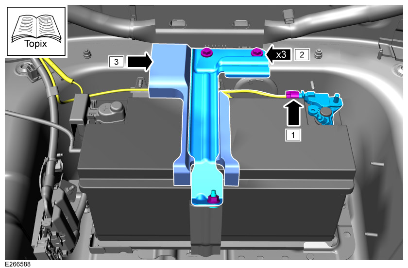
  1. Disconnect the negative battery terminal connector from the startup battery.
  2. Remove the battery bracket and x3 fixings.
  3. Remove the rubber foam.
8

Raise vehicle on ramp.

9
WARNING
  • Requires the aid of another person.

Remove the rear bumper.

  • For additional information, please refer to the official Workshop Manual. Rear Bumper - Vehicles With: Core Specification (501-19 Bumpers)
10
WARNING
  • Observe due care when working near a hot exhaust system.
CAUTION
  • Make sure the exhaust system is supported at all times with workshop stand.

Drop rear exhaust sufficiently enough to gain access to area between rear silencer and rear floor for installation of fixings (E1) in step 16.

  1. 3.0L Diesel. For additional information, please refer to the official Workshop Manual. Rear Silencer (309-00 Exhaust System - INGENIUM I6 3.0L Diesel)
  2. 2.0L Diesel. For additional information, please refer to the official Workshop Manual. Rear Silencer (309-00 Exhaust System - INGENIUM I4 2.0L Diesel AJ21)
  3. 2.0L Petrol. For additional information, please refer to the official Workshop Manual. Rear Silencer (309-00 Exhaust System - INGENIUM I4 2.0L Petrol/INGENIUM I4 2.0L Petrol - PHEV)
  4. 3.0L Petrol. For additional information, please refer to the official Workshop Manual. Exhaust System (309-00 Exhaust System - INGENIUM I6 3.0L Petrol)
  5. PHEVFor additional information, please refer to the official Workshop Manual. Rear Silencer (309-00 Exhaust System - INGENIUM I6 3.0L Diesel)
11
NOTE
  • Exhaust is removed from the illustration to only provide extra clarity.

Remove one or two exhaust heatshields depending on vehicle specification with x3 fixings for each heatshield.

12
WARNING
  • Requires the aid of another person.

Remove the rear armature.

  • For additional information, please refer to the official Workshop Manual. Rear Armature (501-19 Bumpers)
13
CAUTION
  • 'ONLY' hand tighten fixings.

Install the x2 towbar brackets (E) and (F) to vehicle with fixings (E1).

14
WARNING
  • Requires the aid of another person.
CAUTION
  • 'ONLY' hand tighten fixings.

Install the towbar (G) to vehicle with fixings (G1).

15

Tighten the towbar fixings (G1) in this order as illustrated.

  • Torque: 170Nm
16

Tighten the towbar bracket fixings (E1) in this order as illustrated on both sides of the vehicle.

  • Torque: Stage 1: 100Nm, Stage 2: 240° +/- 5°
17

Install one or two exhaust heatshields depending on vehicle specification with x3 fixings for each heatshield.

  • Torque: 10Nm
18

Install the rear exhaust.

  1. 3.0L Diesel. For additional information, please refer to the official Workshop Manual. Rear Silencer (309-00 Exhaust System - INGENIUM I6 3.0L Diesel)
  2. 2.0L Diesel. For additional information, please refer to the official Workshop Manual. Rear Silencer (309-00 Exhaust System - INGENIUM I4 2.0L Diesel AJ21)
  3. 2.0L Petrol. For additional information, please refer to the official Workshop Manual. Rear Silencer (309-00 Exhaust System - INGENIUM I4 2.0L Petrol/INGENIUM I4 2.0L Petrol - PHEV)
  4. 3.0L Petrol. For additional information, please refer to the official Workshop Manual. Exhaust System (309-00 Exhaust System - INGENIUM I6 3.0L Petrol)
  5. PHEVFor additional information, please refer to the official Workshop Manual. Rear Silencer (309-00 Exhaust System - INGENIUM I6 3.0L Diesel)
19

Lower vehicle on ramp.

20
NOTE
  • This illustration is showing certain components removed to provide extra clarity.

Remove grommet from spare wheel well.

21

Follow steps depending on if you have the 'Deployable Side Steps' installed or not.

  • For vehicles 'WITH' deployable side steps see steps 22 to 29. Then continue to step 32.
  • For vehicles 'WITHOUT' deployable side steps see steps 30 to 31. Then continue to step 32.
22
NOTE
  • This step only applies to vehicles 'WITH' deployable side steps installed.

Disconnect x2 connectors, ground cable and cut x3 cable ties from deployable side step link cable (X).

23
NOTE
  • This step only applies to vehicles 'WITH' deployable side steps installed.

Cut x4 cable ties from deployable side step link cable (X).

24
NOTE
  • This step only applies to vehicles 'WITH' deployable side steps installed.

Release the deployable side step link cable (X).

  1. Pull back the right side trim panel and release x2 body harness clips from the studs.
  2. Release the deployable side step link cable (X) from the x2 studs.
25
NOTE
  • This step only applies to vehicles 'WITH' deployable side steps installed.

Cut cable tie and release the rear junction box from the bottom clips.

26
NOTE
  • This step only applies to vehicles 'WITH' deployable side steps installed.

Remove the deployable side step link cable (X).

  1. Remove the deployable side step link cable (X)connector C4BR02R from the rear junction box at position 'C15'.
  2. De-pin the deployable side step blue/red wire (X) from connector C4BR02R cavity 4.
  3. Remove the deployable side step link cable (X) from the vehicle.
27
NOTE
  • This step only applies to vehicles 'WITH' deployable side steps installed.

Disconnect the deployable side step harness (Y) from RBM.

28
NOTE
  • This step only applies to vehicles 'WITH' deployable side steps installed.

Disconnect the deployable side step harness (Y) from RBM.

29
NOTE
  • This step only applies to vehicles 'WITH' deployable side steps installed.

Install the TBM(B) to the foam mounting block.

30
NOTE
  • This step only applies to vehicles 'WITHOUT' deployable side steps installed.

Pull back left side loadspace trim panel and install the foam mounting block(A) to body with x2 fixings (A1).

31
NOTE
  • This step only applies to vehicles 'WITHOUT' deployable side steps installed.

Install TBM(B) to the foam mounting block.

32

Familiarize yourself with towing harness (C).

33

Feed towing harness (C) through spare wheel well.

  1. Section 1 needs to sit inside the vehicle with grommet (CG) sitting against the spare wheel well.
  2. Section 2 needs to sit on the outside of vehicle.
34

Follow steps depending on if your vehicle is a PHEV or 'NOT'.

  1. If your vehicle is a PHEV follow steps 35 to 37. Then proceed to step 39.
  2. If your vehicle is a non-PHEV follow step 38. Then proceed to step 39.
35
NOTE
  • This step 'ONLY' applies to vehicles that are PHEV.

Release x2 body harness clips from the spare wheel well in preparation of initialling the towing harness.

36
NOTE
  • This step 'ONLY' applies to vehicles that are PHEV.
  • Note of how the harness is routed in the illustration.

Install towing harness (C).

  1. Make sure grommet (CG) is installed to spare wheel well securely.
  2. Connect clips (CF), (CH) and (CI)to spare wheel well studs.
  3. Remove existing nut (C5) from the vehicle stud and install ground leads to ring terminal (CE) and place on the vehicle stud. Then reinstall nut (C5) (Torque: 10Nm) to secure the ring terminal.
37
NOTE
  • This step 'ONLY' applies to vehicles that are PHEV.
  • Note of how the harness is routed in the illustration.

Reinstall x2 body harness clips to spare wheel well studs.

38
NOTE
  • This step 'ONLY' applies to vehicles that are NON - PHEV.

Install towing harness (C).

  1. Make sure grommet (CG) is installed to spare wheel well securely.
  2. Connect clips (CF), (CH) and (CI)to spare wheel well studs.
  3. Remove existing nut (C5) from the vehicle stud and install ground leads to ring terminal (CE) and place on the vehicle stud. Then reinstall nut (C5) (Torque: 10Nm) to secure the ring terminal.
39

Install towing harness (C).

  1. Connect towing harness to TBM with connectors (CA), (CB) and (CS).
  2. Clip towing harness to back of bracket with clip ( C V).
  3. Connect connector (CD) to main body harness. If a connector is already installed in this location, then just disconnect it and install (CD).
  4. Connector (CC) is only required if you also have a deployable side step installed. And will be installed later in the procedure.
  5. Secure towing harness to main body harness with x3 cable ties (C1).
40
NOTE
  • This step only applies to vehicles 'WITH' deployable side steps installed. If your vehicle does not have deployable side steps continue from step 45.

Place the RBM foam mounting block (K) onto the existing TBM foam mounting block.

41
NOTE
  • This step only applies to vehicles 'WITH' deployable side steps installed.

Place RBM to foam mounting block.

42
NOTE
  • This step only applies to vehicles 'WITH' deployable side steps installed.

Attach towbar harness connector (CC) to RBM.

  1. Remove towbar connector (CC) from location shown.
  2. Connect towbar connector to the RBM.
43
NOTE
  • This step only applies to vehicles 'WITH' deployable side steps installed.
  • These x3 cable ties will be included in the deployable side steps accessory kit. If you are reinstalling the harness you will need to resource these x3 cable ties from elsewhere.

Reconnect the RBM harness back to the RBM and secure with x3 cable ties (C1).

44

Secure the towing harness with x6 cable ties (C1). Also note position of where connector (CW) is.

45

Connect the female end of link cable (D) to connector (CW).

46
NOTE
  • 'Action 1' has already been done if you completed 'Step 24'. Complete 'Actions 2 and 3'.

Pull back right side trim panel and install towing harness (C).

  1. Remove body harness stud clips x2 from right side of loadspace .
  2. Feed towing harness through clips annotated (*), Install towing harness to 2 studs with fixings (CJ and CK). And cable tie at position (C1).
  3. Install body harness back to the x2 studs.
47
NOTE
  • This step has already been done if you completed 'Step 25'

Cut the cable tie and release junction box from the bottom clips.

48
NOTE
  • 'Action 1' has already been done if you completed 'Step 26' .
  • For junction box connector C15 - C4BR02R, observe orientation of the connector as illustrated when inserting pins.

Install the towing harness to the back of the rear junction box with connector pins (CL).

  1. Remove connector C4BR02R from the rear junction box at position 'C15'.
  2. Remove the protective sleeve from the end of connector pins (CL) on harness (C).
  3. Insert red wire into cavity 1 in connector C4BR02R.
  4. Insert blue/red wire into cavity 4 in connector C4BR02R.
  5. Insert yellow/red wire into cavity 5 in connector C4BR02R.
  6. Insert gray/yellow wire into cavity 6 in connector C4BR02R.
  7. Connect connector C4BR02R back into the rear junction box in position 'C15'.
49

Reconnect rear junction box by the lower clips (a clicking sound will alert you it is securely in place), and then cable tie (C1).

50

Connect fuses.

  1. Fuse (C2) = F71.
  2. Fuses (C3) = F67 and F68.
  3. Relay (C4) = R7.
51

Install the towing harness (C) to towbar as illustrated.

52

Connect 12V startup battery and install battery bracket.

  1. Install the rubber foam.
  2. Install the battery bracket x3 fixings.
  3. Connect the negative battery terminal connector from the 12V startup battery. For additional information, please refer to the official Workshop Manual. Startup Battery Disconnect and Connect (414-00 Battery and Charging System - General Information)
53
NOTE
  • Make sure'Action 1' is successfully completed before proceeding to'Action 2'.

Use the JLR approved diagnostic equipment to navigate to 'Diagnostics' section and follow the steps below.

  1. Within Vehicle Applications – Click ‘RUN’ for ‘Add/Remove Electronically Deployable Towbar’, then choose ADD.
  2. Within Module Programing – Click ‘RUN’ for ‘TBM - Software - Replace Module’.
  3. To enable the changes on the vehicle
    Ignition off
    Close all doors
    Lock the vehicle
    Wait 5 minutes
    To confirm changes
    Unlock the vehicle
    Reset Infotainment Screen (Refer to 'Touchscreen' settings in Owners handbook for detailed procedure.)
    Confirm ‘Tow bar' tile is present on the Touchscreen.
54

Install the rear bumper support bracket with x7 fixings.

  • Torque: 10Nm.
55

Install the obstacle detection control module assembly on both sides of the vehicle.

  1. Install x2 fixings. Torque: 10Nm.
  2. Secure harness with x2 clips.
  3. Connect the x2 connectors.
56

Install the antenna module and harness.

  1. Install the antenna module to the bumper support bracket with x2 bolts. Torque: 10Nm.
  2. Connect the harness to antenna module and secure harness to bumper support bracket with x5 clips.
57
NOTE
  • When Installing the rear bumper the new towbar valance (H) will replace the old one.

Install rear bumper with new towing valance (H) and secure with x3 clips (H1).

  • For additional information, please refer to the official Workshop Manual. Rear Bumper - Vehicles With: Core Specification (501-19 Bumpers)
58

Install the deployable towbar switch (J) to the left side upper trim panel in the vehicle.

  1. Remove existing blanking bezel and the rear height adjust switch (if present) from the left side upper trim panel.
  2. Install the switch bezel (I). Then click in the switch (J) and the height adjust switch (if present).
59

Install both left and right side trim panel by installing x4 fixing clips on each side.

60
NOTE
  • When reinstalling the C-pillar and D-pillar upper trims with the newly installed switch (J). Make sure that the switch (J) is connected to the male connector of harness (D) that was installed in step 45.

Install C-pillar and D-pillar upper trims on both sides of the vehicle.

  • For additional information, please refer to the official Workshop Manual. C-Pillar and D-Pillar Upper Trim Panel (501-05 Interior Trim and Ornamentation)
61

Install the loadspace scuff plate trim panel.

  • For additional information, please refer to the official Workshop Manual. Loadspace Scuff Plate Trim Panel (501-05 Interior Trim and Ornamentation)
62

Install parts in this order.

  1. Install the spare wheel (if applicable).
  2. Install the tool foam tray.
63

Install parts in this order.

  1. Install the loadspace floor.
  2. Install the loadspace D-loops. Torque: 24Nm.
  3. Install the parcel shelf.
  4. Fold up the second row seats and close tailgate.
64

Inspect the operation of the trailer lamps and the vehicle lamps. Both trailer and vehicle lamps must be synchronised.

65

Motor Vehicle Data Sheet

Motor vehicle data, Deployable Towbar Specifications
Type Coil: 5918, Air: 5744
D-value 12.76kN
Vertical coupling load 175kg
Coupling class A50-X
Manufacturer Brink Towing Systems B.V.
Model application Range Rover Velar
EC-type approval number towbar: Coil E11 55R-0110635
EC-type approval number towbar: Air E11 55R-0110634
Maximum trailer weight 2500kg (2000kg PHEV)
© Land Rover 2016