LAND ROVER ACCESSORY FITTING INSTRUCTIONS

VEHICLE :
PART NO :
KEYWORD :

LAND ROVER

FITTING INSTRUCTION

WARNING
  • Accessories which are not correctly installed can be dangerous. Read the instructions carefully prior to installation. Comply with instructions at all times. If in doubt, contact your nearest approved retailer.
CAUTION
  • Towbars installed in conjunction with deployable side steps are only applicable to 'Detachable Towbar' in these instructions. This option will not be available for the 'NAS' and 'Australian' markets.

Detachable Towbar (Bill of Materials)

NOTE
  • Detachable towbar comes in 2 different kits. VPLYT0296 are for vehicles that come with coil suspension and VPLYT0297 are vehicles that come with air suspension. Installation process of both are identical.
  • Item (A) VPLYT0338 will not need to be ordered if you already have deployable side steps installed to your vehicle.
  • Item (J) VPLYT0340 will only need to be ordered if you already have deployable side steps installed to your vehicle.
  • The bag for storing the detachable towbar (I) only comes in kit (VPLYT0296).
Description Specifications
Type Towbar: 5742, Ball (Coil): 9078663, Ball (Air): 9078662
D-value 12.76kN
Vertical coupling load 175kg
Coupling class A50-X
Manufacturer Brink Towing Systems B.V.
Model application Range Rover Velar
EC-type approval number towbar: E11 55R-0110644
EC-type approval number tow ball: (Air) E11 55R-0110633
EC-type approval number tow ball: (Coil) E11 55R-0110632
Maximum trailer weight 2500kg (2000kg Plug-in Hybrid Electric Vehicle (PHEV) )

Australian towbar (Bill of Materials)

Description Specifications
Type Towbar: 5960, Coil: 9078663, Air: 9078662
D-value 12.76Kn
Vertical coupling load 175kg
Coupling class A50-X
Manufacturer Brink Towing Systems B.V.
Model application Range Rover Velar
Maximum trailer weight 2500kg (2000kg PHEV)

NAS towbar (Bill of Materials)

Description Specifications
Type Towbar: 5743, Coil: 9078663, Air: 9078662
D-value 12.76Kn
Vertical coupling load 175kg
Coupling class A50-X
Manufacturer Brink Towing Systems B.V.
Model application Range Rover Velar
Maximum trailer weight 2500kg (2000kg PHEV)
REMOVAL INSTRUCTIONS
1

Fold down second row seats. Please see Owner's Handbook if unsure how to do this.

2
NOTE
  • Appearance of the loadspace stowage compartment will vary depending on the vehicle specification.

Remove parts in this order.

  1. Remove loadspace cover.
  2. Remove loadspace D-loops.
  3. Remove loadspace floor.
3
NOTE
  • Appearance of the loadspace stowage compartment will vary depending on the vehicle specification.

Remove parts in this order.

  1. Remove spare wheel (if applicable).
  2. Remove tool foam tray.
4

Remove loadspace scuff plate trim panel.

  • For additional information, please refer to the official Workshop Manual. Loadspace Scuff Plate Trim Panel (501-05)
5

Remove left and right C-pillar and D-pillar upper trims.

  • For additional information, please refer to the official Workshop Manual. C-Pillar and D-Pillar Upper Trim Panel (501-05)
6

Partially remove both left and right side trim panel by removing fixing clips for access.

7
WARNING
  • Always follow the workshop procedure to disconnect the PHEV 12V start up battery.
NOTE
  • Appearance of the battery will vary depending on the vehicle specification, but the essential information is always correct.

Disconnect 12V start up battery and remove battery bracket.

  1. Disconnect negative battery terminal connector from the 12V start up battery. For additional information, please refer to the official Workshop Manual. Startup Battery Disconnect and Connect (414-00)
  2. Remove battery bracket x3 fixings.
  3. Remove rubber foam.
8

Raise vehicle on 4 post ramp.

9
WARNING
  • Requires the aid of another person.

Remove rear bumper.

  • For additional information, please refer to the official Workshop Manual. Rear Bumper - Vehicles With: Core Specification (501-19)
10
WARNING
  • Observe due care when working near a hot exhaust system.
CAUTION
  • Make sure the exhaust system is supported at all times with workshop stand.
NOTE
  • This step shows the variants of diesel exhaust systems.

Drop rear exhaust sufficiently enough to gain access to area between rear silencer and rear floor for installation of fixings (E1) in install step 1.

  1. 3.0L Diesel. For additional information, please refer to the official Workshop Manual. Rear Silencer (309-00E)
  2. 2.0L Diesel. For additional information, please refer to the official Workshop Manual. Rear Silencer (309-00B)
11
WARNING
  • Observe due care when working near a hot exhaust system.
CAUTION
  • Make sure the exhaust system is supported at all times with workshop stand.
NOTE
  • This step shows the variants of petrol exhaust systems.

Drop rear exhaust sufficiently enough to gain access to area between rear silencer and rear floor for installation of fixings (E1) in install step 1.

  1. 2.0L Petrol. For additional information, please refer to the official Workshop Manual. Rear Silencer (309-00A)
  2. 3.0L Petrol. For additional information, please refer to the official Workshop Manual. Rear Silencer (309-00D)
12
WARNING
  • Observe due care when working near a hot exhaust system.
CAUTION
  • Make sure the exhaust system is supported at all times with workshop stand.
NOTE
  • This step shows the PHEV exhaust system.

Drop rear exhaust sufficiently enough to gain access to area between rear silencer and rear floor for installation of fixings (E1) in install step 1.

  • PHEVFor additional information, please refer to the official Workshop Manual. Rear Silencer (309-00E)
13

Remove one or two exhaust heatshields depending on vehicle specification with x3 fixings for each heatshield.

14
WARNING
  • Requires the aid of another person.

Remove rear armature.

  • For additional information, please refer to the official Workshop Manual. Rear Armature (501-19)
Fitting Instruction
1
CAUTION
  • At this stage only hand tighten fixings.

Install towbar brackets (E) and (F) to vehicle with fixings (E1).

2
WARNING
  • Requires the aid of another person.
CAUTION
  • At this stage only hand tighten fixings.

Install towbar (G) to vehicle with fixings (G1).

3

Tighten towbar fixings in this order as illustrated.

  • Torque: 170 Nm
4

Tighten towbar bracket fixings in this order as illustrated on both sides of the vehicle.

  • Torque: Stage 1: 100Nm, Stage 2: 240° +/- 5°
5

Install one or two exhaust heatshields depending on vehicle specification with x3 fixings for each heatshield.

  • Torque: 10Nm
6

Install rear exhaust system.

7

Lower vehicle.

8
NOTE
  • This illustration is showing certain components removed to provide extra clarity.

Remove grommet from spare wheel well.

9

Follow steps depending on if you have deployable side steps installed or not.

  1. For vehicles 'WITH' deployable side steps already installed see steps 10 to 17. Then continue to step 20.
  2. For vehicles 'WITHOUT' deployable side steps installed see steps 18 to 19. Then continue to step 20.
10
NOTE
  • This step is only applicable to vehicles 'WITH' deployable side steps installed.

Remove existing deployable side step link cable (X). Disconnect x2 connectors, earth cable and x3 cable ties.

11
NOTE
  • This step is only applicable to vehicles 'WITH' deployable side steps installed.

Continue to remove existing deployable side step link cable (X). Disconnect x4 cable ties.

12
NOTE
  • This step is only applicable to vehicles 'WITH' deployable side steps installed.

Pull back right side trim panel and remove deployable side step link cable (X).

  1. Remove body harness stud clips x2 from right side of loadspace.
  2. Remove deployable side step link cable (X) from the x2 clips.
13
NOTE
  • This step is only applicable to vehicles 'WITH' deployable side steps installed.

Cut cable tie and release rear junction box from bottom clips.

14
NOTE
  • This step is only applicable to vehicles 'WITH' deployable side steps installed.
  • For the junction box connector C15 - C4BR02R, observe orientation of the connector as illustrated when removing pins.

Remove the deployable side step link cable (X) from the back of the rear junction box.

  1. Remove connector C4BR02R from the rear junction box at position 'C15'.
  2. De-pin deployable side step blue/red wire (X) from connector C4BR02R cavity 4.
15
NOTE
  • This step is only applicable to vehicles 'WITH' deployable side steps installed.

Disconnect deployable side step harness from Running Board Control Module (RBM) .

16
NOTE
  • This step is only applicable to vehicles 'WITH' deployable side steps installed.

Remove RBM from module holder.

17
NOTE
  • This step is only applicable to vehicles 'WITH' deployable side steps installed.

Install Tow Bar Control Module (TBM) (B) to module holder.

18
NOTE
  • This step is only applicable to vehicles 'WITHOUT' deployable side steps installed.

Pull back left side loadspace trim panel and install module holder (A) to body with fixings (A1).

19
NOTE
  • This step is only applicable to vehicles 'WITHOUT' deployable side steps installed.

Pull back left side loadspace trim panel and install module holder (A) to body with fixings (A1).

  1. Install TBM (B) to module holder.
20
NOTE
  • For PHEV vehicles only.

Remove x3 body harness clips from spare wheel well in preparation of installing the towing harness (C).

21
NOTE
  • Make note of towing harness (C) connectors and clips.

Familiarize yourself with towing harness (C).

22

Feed towing harness (C) through spare wheel well.

  1. Section 1 needs to sit inside the vehicle with grommet (CG) sitting against the spare wheel well.
  2. Section 2 needs to sit on the outside of vehicle.
23

Follow steps depending on if your vehicle is a PHEV or not.

  1. If your vehicle is a PHEV follow steps 24 to 26. Then proceed to step 28.
  2. If your vehicle is a non-PHEV follow step 27. Then proceed to step 28.
24
NOTE
  • For PHEV vehicles only.
  • Please make note of how the body harness routed on the illustration on top of the towing harness.

Install x1 body harness clip to spare wheel well stud.

25
NOTE
  • For PHEV vehicles only.
  • Please make note of how the harness routed on the illustration.

Install towing harness (C).

  1. Make sure grommet (CG) is installed to spare wheel well securely.
  2. Connect clips (CF), (CH) and (CI) to spare wheel well studs.
  3. Remove existing nut (C5) and install earth leads to ring terminal (CE) to (C5) stud and reinstall nut (C5).
  4. Torque: 10Nm
26
NOTE
  • For PHEV vehicles only.
  • Please make note of how the harness routed on the illustration.

Reinstall x2 body harness clips to spare wheel well studs.

27
NOTE
  • For non-PHEV vehicles only.

Install towing harness (C).

  1. Make sure grommet (CG) is installed to spare wheel well securely.
  2. Connect clips (CF), (CH) and (CI) to spare wheel well studs.
  3. Remove existing nut (C5) and install earth leads to ring terminal (CE) to (C5) stud and reinstall nut (C5).
  4. Torque: 10Nm
28

Install towing harness (C).

  1. Connect connectors (CA) and (CB) to Trailer Module (TRM) .
  2. Connect connector (CD) to main body harness. If a connector is already installed in this location, then just disconnect it and install (CD).
  3. Connector (CC) is only required if you also have a deployable side step installed.
  4. Cable tie harness with x3 cable ties (C1).
29

The follow steps 30 to 33 are only for vehicles with deployable side steps already installed. If your vehicle does not have deployable side steps then proceed to step 34.

30
NOTE
  • For vehicles 'WITH' deployable side steps installed.

Place the RBM carrier (J) onto the existing towbar module carrier.

31
NOTE
  • For vehicles 'WITH' deployable side steps installed.

Place RBM to module holder (J).

32
NOTE
  • For vehicles 'WITH' deployable side steps installed.

Attach towbar harness connector (CC) to RBM.

  1. Remove towbar connector (CC) from location shown.
  2. Connect towbar connector to the RBM.
33
NOTE
  • For vehicles 'WITH' deployable side steps installed.

Reconnect the RBM harness back to the RBM and secure with x3 cable ties (C1).

34
NOTE
  • Step 1 has already been done if you already removed an existing deployable side step harness.

Pull back right side trim panel and install towing harness (C).

  1. Remove body harness stud clips x2 from right side of loadspace.
  2. Cable tie (C1) then feed the remaining towing harness through clips annotated (*), and install towing harness to x2 studs with fixings (CJ and CK).
  3. Install body harness back to the x2 studs.
35
NOTE
  • This step has already been done if you already have deployable side steps installed.

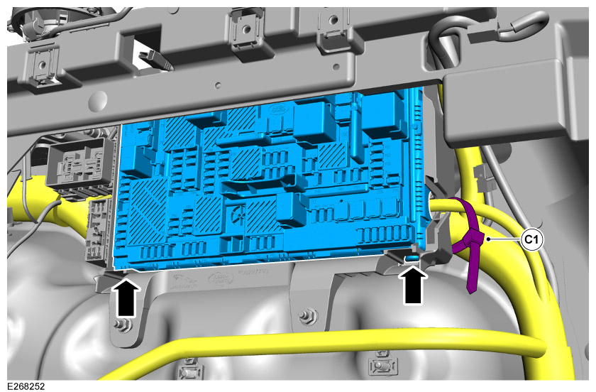
Cut cable tie and release junction box from bottom clips.

36
NOTE

Install the towing harness (C) to the back of the rear junction box with connector pins (CL).

  1. Remove connector C4BR02R from the rear junction box at position 'C15'.
  2. Remove the protective sleeve from the end of connector pins (CL) on harness (C).
  3. Insert red wire into cavity 1 in connector.
  4. Insert blue/red wire into cavity 4 in connector.
  5. Insert yellow/red wire into cavity 5 in connector.
  6. Insert gray/yellow wire into cavity 6 in connector.
  7. Connect connector back into the rear junction box in position 'C15'.
37

Reconnect junction box by the lower clips (a clicking sound will alert you it is securely in place), and then cable tie (C1).

38

Connect fuses.

  1. Fuse (C2) = F71.
  2. Fuses (C3) = F67 and F68.
  3. Relay (C4) = R7.
39

Install towbar harness to towbar.

40

Connect 12V start up battery and install battery bracket.

  1. Install rubber foam.
  2. Install battery bracket x3 fixings.
  3. Connect negative battery terminal connector from the 12V start up battery. For additional information, please refer to the official Workshop Manual. Startup Battery Disconnect and Connect (414-00)
41

Begin diagnostic procedure in parallel to the following trim installation steps.

  1. Using the Jaguar Land Rover approved diagnostic equipment, update the towbar control module to the latest software.
  2. Using the Jaguar Land Rover approved diagnostics equipment, configure the towbar hardware to enable towing on the vehicle.
  3. To enable the new changes on the vehicle: Switch off the vehicle ignition and close all apertures. Lock the vehicle for 5 minutes.
  4. After 5 minutes unlock the vehicle and perform a hard battery reset. Start the engine and make sure the "TOWBAR" icon is shown on the Touchscreen.
42

Install rear bumper support bracket x7 fixings.

  • Torque: 10Nm
43

Install the antenna module and harness.

  1. Fit antenna module to bumper support bracket with x2 bolts. Torque: 10Nm
  2. Connect harness to antenna module and secure harness to bumper support bracket with x5 clips.
44
NOTE
  • When reinstalling the rear bumper the new towbar valance (H) will replace the old one.

Reinstall rear bumper with new towbar valance (H) and secure with x3 clips (H1).

  • For additional information, please refer to the official Workshop Manual. Rear Bumper - Vehicles With: Core Specification (501-19)
45

Install both left and right side trim panel by installing fixing clips on each side.

46

Install C-pillar and D-pillar upper trims on both sides of the vehicle.

  • For additional information, please refer to the official Workshop Manual. C-Pillar and D-Pillar Upper Trim Panel (501-05)
47

Install loadspace scuff plate trim panel.

  • For additional information, please refer to the official Workshop Manual. Loadspace Scuff Plate Trim Panel (501-05)
48

Install parts in this order.

  1. Install spare wheel (if applicable).
  2. Install tool foam tray.
49

Install parts in this order.

  1. Install loadspace floor.
  2. Install loadspace D-loops. Torque: 24Nm
  3. Install parcel shelf.
50

Fold up second row seats.

51
NOTE
  • Detachable towbar only.

To install the detachable ball please refer to the Owner's Handbook.

52
NOTE
  • NAS and Australian towbar only.

Install tow ball.

  1. Remove dirt cover (D).
  2. Insert tow ball (I) into socket.
  3. Insert locking hitch pin through hole and lock with key.
53
NOTE
  • Detachable towbar storage for non-PHEV vehicles only.

When not using the detachable ball (I) and dirt cover (D) you can store in the tool foam tray under the loadspace cover.

  1. Vehicles without a spare wheel.
  2. Vehicles with a spare wheel.
54
NOTE
  • Detachable towbar storage for PHEV vehicle only.

Use the bag in the kit to store the detachable ball (I). Then tie the bag to one of the D-loops in the loadspace as illustrated.

55

Check for Diagnostic Trouble Code(s) (DTC) on Pathfinder.

56

Check the operation of the trailer lamps and the vehicle lamps. Both trailer and vehicle lights must be synchronised.

© Land Rover 2016