Scan the QR code or use the link https://animations.cloudproduct.info/bracket/ for a step by step fixings installation animation with tool (D). If you have a 'Torque Wrench' then that can be used instead of tool (D) and skip the animation and proceed from 'Step 13'.
- (Action 1 of the animation) Hand tighten LH fixing. See 'Step 13' in these instructions for further information if required.
- (Action 2 of the animation) Hand tighten RH fixing. See 'Step 14' in these instructions for further information if required.
- (Action 3 of the animation) For LH fixing. Place only the thumb and index finger onto the end of tool (D) (not in the tool hole) and pinch tightly. Then place tool (D) onto the fixing and begin to tighten until fingers slip of the tool naturally. Then use tool (D) to tighten 90° (align 90° with bumper to aid in getting the correct angle). Then untighten fixing 90° before proceeding to the next action.
- (Action 4 of the animation) For RH fixing. Place only the thumb and index finger onto the end of tool (D) (not in the tool hole) and pinch tightly. Then place tool (D) onto the fixing and begin to tighten until fingers slip of the tool naturally. Then use tool (D) to tighten 90° (align 90° with bumper to aid in getting the correct angle). Then untighten fixing 90° before proceeding to the next action.
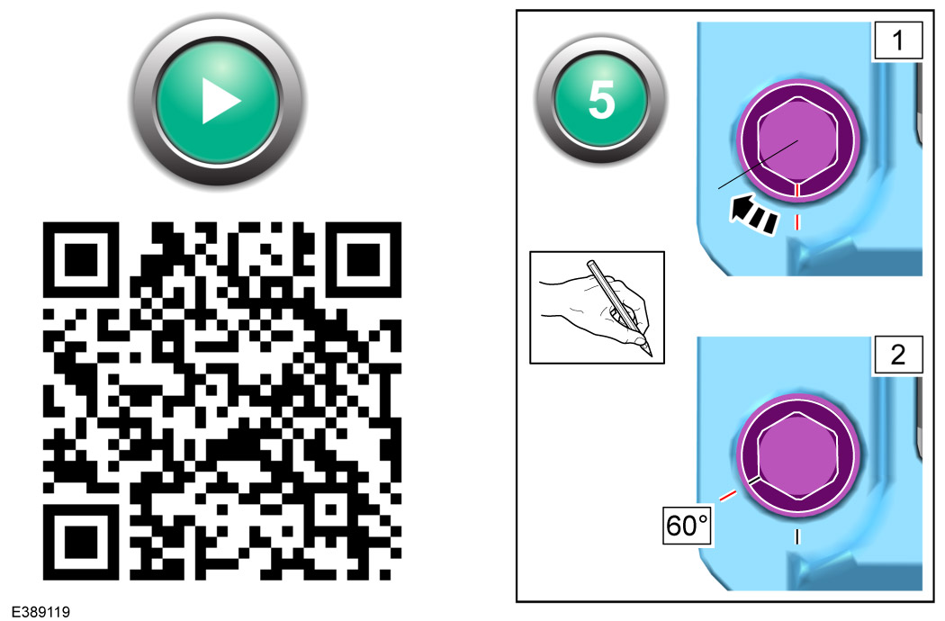
- (Action 5 of the animation) For LH fixing. Place only the thumb and index finger onto the end of tool (D) (not in the tool hole) and pinch tightly. Then place tool (D) onto the fixing and begin to tighten until fingers slip of the tool naturally. Then use tool (D) to tighten 60° (each face on the fixing is 60°. The graphic above will aid you in marking up the correct start and finish position of fixing. Then untighten 60° before proceeding to the next action.
- (Action 6 of the animation) For RH fixing. Place only the thumb and index finger onto the end of tool (D) (not in the tool hole) and pinch tightly. Then place tool (D) onto the fixing and begin to tighten until fingers slip of the tool naturally. Then use tool (D) to tighten 60° (each face on the fixing is 60°. The graphic above will aid you in marking up the correct start and finish position of fixing. Then untighten 60° before proceeding to the next action.
- (Action 7 of the animation) For LH fixing. Place only the thumb and index finger onto the end of tool (D) (not in the tool hole) and pinch tightly. Then place tool (D) onto the fixing and begin to tighten until fingers slip of the tool naturally. Then use tool (D) to do a final tighten of 60° (use the markings made in the previous actions to aid you in the correct torque).
- (Action 8 of the animation) For RH fixing. Place only the thumb and index finger onto the end of tool (D) (not in the tool hole) and pinch tightly. Then place tool (D) onto the fixing and begin to tighten until fingers slip of the tool naturally. Then use tool (D) to do a final tighten of 60° (use the markings made in the previous actions to aid you in the correct torque).
- Installation complete. The remaining steps in these instructions are only for installation with a 'Torque Wrench' only and not required if you have followed the animation.