LAND ROVER ACCESSORY FITTING INSTRUCTIONS

VEHICLE :
PART NO :
KEYWORD :

LAND ROVER

DEFENDER

FIXED SIDE STEPS

VPLEP0391 / VPLEP0514 / VPLEP0392 / VPLEP0513 / VPLEP0524 / VPLEP0525

FITTING INSTRUCTION

WARNING
  • Accessories which are not correctly installed can be dangerous.
  • Before ordering and installing the accessory, you must read all the instructions. The correct accessory / part must be ordered for you variant of the vehicle.
  • You must follow all instructions. If in doubt, contact your nearest approved retailer.
NOTE
  • Older and newer edition part numbers may be present for the same kit. Latest edition is recommenced, but all are acceptable to order and install, depending on stock levels.
Kits Required Edition 1 Part Number Edition 2 Part Number
Fixed Side Steps (Silver / Black) - Defender 90 VPLEP0391 VPLEP0524
Fixed Side Steps (Black) - Defender 90 VPLEP0514
Fixed Side Steps (Silver / Black) - Defender 110/130 VPLEP0392 VPLEP0525
Fixed Side Steps (Black) - Defender 110/130 VPLEP0513

Side Protection Tubes (Bill of Materials)

NOTE
  • The table(s) below are a breakdown of the accessory kit contents. They include individual parts, quantities and if required replacement service part numbers for specific parts.
  • The quantity of spacers (G) will change depending on the kit you have ordered from the table above. There will be x8 spacers for Defender 90 kits and x4 spacers for Defender 110/130 kits.
  • The bill of materials shows the Defender 110/130 side steps. The Defender 90 bill of materials is similar, with the visual difference being the side steps.
Contents Replacement Part Numbers
(A) Side Steps
(B) Front Brackets
(C) Rear Brackets
(D) Fixing - M10x60 LR152410
(E)Fixing - M8x28 LR135788
(F) Fixing - M6x23 LR141748
(G) Spacers

Additional Trim Clips

NOTE
  • Trim clips - LR112137 can be ordered as required if original clips are damaged during removal of the exterior body trims. The maximum quantity that may be required is x30 for both sides of the vehicle.

Warnings / Cautions / Notes / Tooling and Equipment

WARNING
  • You must wear suitable personal protective equipment when cutting / drilling parts.
CAUTION
  • Installing side steps will affect the off-road capability of the vehicle.
  • When discarding parts do so in an environmentally responsible manner making sure all local laws are adhered to.
NOTE
  • If you are installing 'Front Mudflaps' with the 'Side Steps' then they must be installed after the 'Side Steps' are installed.
  • If 'Front Mudflaps' are already installed then these must be removed before installing the 'Side Steps'.
  • This procedure contains some variation in the illustrations depending on the vehicle specification, but the essential information is always correct.
  • This procedure contains illustrations for left side components, right side components are install in a similar manner.
  • Install only one 'side step' at a time before installing to the other side of the vehicle.
Tooling and Equipment
Torque Wrench
Socket Set
Torx Set
Plastic Trim Removal Tool
Oscillator cutting tool
Ruler
Pen / Pencil
Fitting Instruction
1

Open all doors and raise and support the vehicle.

  • Log into TOPIX and enter 'Vehicle Identification Number' and navigate to 'Workshop Manual' section '100-02 Jacking and Lifting'.
2
NOTE
  • Make sure that the x4 clips remain on the front fender moulding. Replace any broken clips as required with clips (H).

Remove the front fender mounting.

  • Log into TOPIX and enter character 'Vehicle Identification Number' and navigate to 'Workshop Manual' section '501-08 Exterior Trim and Ornamentation / Front Fender Moulding'.
3
NOTE
  • Replace any broken clips as required with clips (H).
  • Only the outermost fixing needs to be remove on the rear wheel arch finisher panel in the workshop manual link and not all x5 fixings as suggested.

Remove the rocker panel.

  • Log into TOPIX and enter character 'Vehicle Identification Number' and navigate to 'Workshop Manual' section '501-08 Exterior Trim and Ornamentation / Rocket Panel'.
4
NOTE
  • Image will differ depending on vehicle specification.

Remove the transmission shield and side undershields.

  • Log into TOPIX and enter character 'Vehicle Identification Number' and navigate to 'Workshop Manual' section '501-02 Front End Body Panels / Left Undershield'.
  • Log into TOPIX and enter character 'Vehicle Identification Number' and navigate to 'Workshop Manual' section '501-02 Front End Body Panels / Right Undershield'.
5
NOTE
  • Image will differ depending on vehicle specification. The cut locations will be closer together on the Defender 90.

Modify both rocker panels. The left side is shown, but the right side is the same.

  1. Identify the cut guide lines on the left side rocker panel. Paint over them to make them clearer.
  2. Drill holes at the illustrated locations (1).
  3. Use suitable tooling to cut the illustrated sections (2) from the left side rocker panel. Then discard the removed sections.
6
NOTE
  • Image will differ depending on vehicle specification. The marked locations will be closer together on the Defender 90.

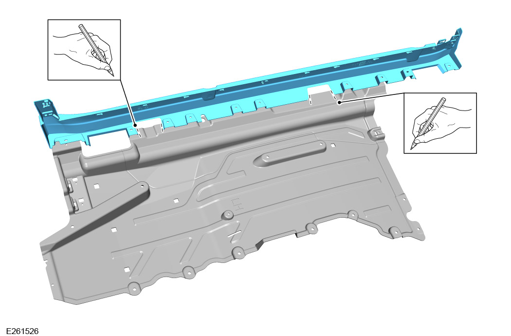
Mark up both side undershields. The left side is shown, but the right side is the same.

  1. Position the side rocker panel over the top of the undershield as illustrated, lining up the original fixing positions.
  2. Inspect that the holes in the rocker panel align with the matching holes in the side undershield.
  3. Mark lines on the undershield as shown, using the rocker panel as a template.
7
NOTE
  • Image will differ depending on vehicle specification. The cut locations will be closer together on the Defender 90.

Modify both side undershields.

  1. Guide lines have a depth of 50 mm as illustrated from the marked positions in the previous step.
  2. Use suitable tooling to cut the illustrated sections from the side undershields. Then discard the removed sections.
8
NOTE
  • This step is 'ONLY' for Defender 90 vehicles.

Remove and discard fixings.

  1. Rest Of World (ROW) - x2 fixings.
  2. North American Specification (NAS) - x3 fixings.
9
NOTE
  • This step is 'ONLY' for Defender 110/130 vehicles.

Remove and discard fixings.

  1. Rest Of World (ROW) - x2 fixings.
  2. North American Specification (NAS) - x3 fixings.
10

Identity side step brackets.

  • The side step brackets are individually labelled with the position on the vehicle they must be installed to.
  • LHF = Left Hand Front (B)
  • RHF = Right Hand Front (B)
  • LHR = Left Hand Rear (C)
  • RHR = Right Hand Rear (C)
11
CAUTION
  • Spacers (G) are only to be used in 'ROW' markets. For 'NAS' markets, they are not required as there is an extra panel that acts as the spacer already installed.
NOTE
  • Front brackets are to be installed in the same location where the front fixings were removed in 'STEP 8 or 9' depending on vehicle variant.

Install the front side step bracket (B).

  1. Install, but do not fully tighten x2 fixings (D) and x2 spacers (G) to fasten front bracket.
  2. Install, but do not fully tighten x2 fixings (E).
12
CAUTION
  • Spacers (G) are only to be used in 'ROW' markets. For 'NAS' markets, only the very rear fixing for Defender 90 requires a spacer. The rest are not required as there is an extra panel that acts as the spacer already installed.
NOTE
  • Rear brackets are to be installed in the same location where the rear fixing was removed in 'STEP 8 or 9' depending on vehicle variant.

Install the rear side step bracket (C).

  1. Install, but do not fully tighten x2 fixings (D) and x2 spacers (G) to fasten front bracket.
  2. Install, but do not fully tighten x2 fixings (E).
13
WARNING
  • This step requires the aid of another technician (heavy part).

Install side step (A).

  1. Offer up side step to the front bracket (B) and rear bracket (C).
  2. Install, but do not fully tighten x6 fixings (F) to install the side step to the bracket.
14
CAUTION
  • Side step brackets may crack when fully tightened if they are not installed correctly.

Inspect before fully tightening fixings.

  • Before fully tightening side step brackets, there must be no gap between the side step brackets and the outer vehicle sill before continuing to the next step.
15
CAUTION
  • If tighten sequence is not followed, this could result in damage to the brackets.

Fully tighten the x4 fixings (E) in the sequence shown.

  1. Rear bracket - Tighten fixing (1) first and then fixing (2). Torque: 24Nm
  2. Front bracket - Tighten fixing (1) first and then fixing (2). Torque: 24Nm
16
CAUTION
  • Do not use a impact applicator.

Fully tighten the x4 fixings (D) Torque: 64Nm.

17
WARNING
  • This step requires the aid of another technician (heavy part).

Remove the side step (A).

  • Remove x6 fixings (F) to remove the side step.
18
NOTE
  • Image will differ depending on vehicle specification.

Install the transmission shield and side undershields.

  • Log into TOPIX and enter character 'Vehicle Identification Number' and navigate to 'Workshop Manual' section '501-02 Front End Body Panels / Left Undershield'.
  • Log into TOPIX and enter character 'Vehicle Identification Number' and navigate to 'Workshop Manual' section '501-02 Front End Body Panels / Right Undershield'.
19

Install the rocker panel.

  • Log into TOPIX and enter character 'Vehicle Identification Number' and navigate to 'Workshop Manual' section '501-08 Exterior Trim and Ornamentation / Rocket Panel'.
20

Install the front fender mounting.

  • Log into TOPIX and enter character 'Vehicle Identification Number' and navigate to 'Workshop Manual' section '501-08 Exterior Trim and Ornamentation / Front Fender Moulding'.
21
WARNING
  • This step requires the aid of another technician (heavy part).

Install side step (A).

  1. Offer up side step to the front bracket (B) and rear bracket (C).
  2. Install x6 fixings (F) to install the side step to the bracket. Torque: 10Nm
22

Lower vehicle.

© Land Rover 2016