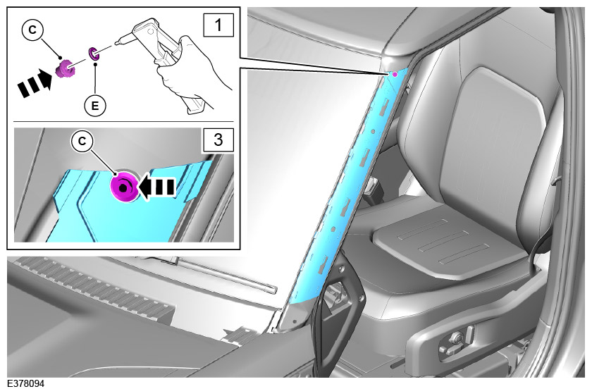
LAND ROVER ACCESSORY FITTING INSTRUCTIONS

VEHICLE :
PART NO :
KEYWORD :

LAND ROVER

DEFENDER

RAISED AIR INTAKE

VPLEP0543

FITTING INSTRUCTION

WARNING
  • Accessories which are not correctly installed can be dangerous. Read the instructions carefully prior to ordering and installation to make sure this accessory is applicable to your variant of vehicle. Comply with instructions at all times. If in doubt, contact your nearest approved retailer.
Kits Required Part Number
Raised Air Intake VPLEP0543

Raised Air Intake - VPLEP0543 (Bill of Materials)

Bill Of Materials Replacement Service Part Numbers
(A) Raised Air Intake Available in complete kit only
(B) Raised Air Intake Cap Available in complete kit only
(C) M6 Rivet Nut LR183020
(D) Fixing M6x20 LR183020
(E) M6 Washer Available in complete kit only
Template Available in complete kit only

Warnings / Cautions / Notes

CAUTION
  • Take care to avoid damage to the vehicle paintwork and exterior finishers.
NOTE
  • The raised air intake is always installed to the left side of the vehicle.

Tooling

Tooling
Oscillating cutting tool
Drill (2, 6 ,8mm)
File or deburring tool
Sharp pick
Scissors
China graph or paint marker
Torque Wrench/Screw Driver (range upto 5Nm)
Trim Removal Tool
Riv Nut Tool
Ruler (for checking scale if required)
Fitting Instruction
1

Use a suitable plastic trim tool to remove and retain the lower section of the A-pillar trim.

  • For additional information, please refer to the official Workshop Manual. A-Pillar Trims (501-08)
2

Use a suitable plastic trim tool to remove and retain the A-pillar trim and fixing.

  1. Remove fixing.
  2. Remove the A-pillar trim by sliding downward first and then lifting away.
3
NOTE
  • x2 clips will need to be retained for the installation later in the instructions.

Open the door and use a suitable plastic trim tool to remove and discard the side vent trim. When pulled away some clips may be left in place in the fender. These will need to be removed.

4

Clean the illustrated area.

5
WARNING
  • Make sure that the rivet nut (C) is correctly formed in the A-pillar, and is checked to make sure it is secure before moving to the next step.
NOTE
  • Washer (E) is required to aid the installation of the riv nut by providing clearance from the a pillar retailer highlighted.

Use a rivet nut installation tool to install the rivet nut (C) to the vehicle body as illustrated.

  1. Install the washer (E) onto the rivet nut tool, then insert the rivet nut (C) to the tool.
  2. There is a sticker over the hole on the vehicle that will need to be pierced before you install the rivet nut.
  3. Install rivet nut (C) to the vehicle. There is a cutout in the A-pillar trim that allows the rivet nut to be installed at the correct location.
  4. Washer (E) can then be removed from the tool and retained.
6
NOTE

Use supplied template and cut out template (A). Then place the template on the inside of the removed A-pillar trim at the top and secure with tape. See the above notes for replacement template if damaged.

7

Using a sharp pick indent the x4 drill centres and the dotted lines on the template. Then remove template.

8

Drill x4 pilot holes (2mm) for the corners. Then enlarge the holes with a (6mm) drill.

9

Using an oscillating cutting tool to cut out marked lines.

10

Clean up the edges using a file or deburring tool.

11

Install the A-pillar trim.

  1. Install the A-pillar trim. Locate onto the A-pillar and then slide upwards.
  2. Install fixing. Torque: 1.3Nm
12

Install the lower section of the A-pillar trim.

13

Install x2 clips that were retained in step 3 and install them to the 'Raised Air Intake' (A).

14

Align and position the raised air intake (A) against the vehicle.

  1. Install the arrowed edge (1) first.
  2. Inspect the alignment of the full height of the raised air intake against the A-pillar.
  3. Install the arrowed rear edge (3) and make sure the clips align with the matching holes in the fender panel. Then push to clip into place (listen for an audible click to signify the clips are securely in place).
15
CAUTION
  • Failure to tighten to the correct torque will result in joint failure.

Install fixing (D).

  • Torque: 4Nm
16

Install the raised air intake cap (B) to the main raised air intake (A), by pushing down and clip into place with x2 clips.

17

Make sure the raised air intake is correctly installed.

  • Make sure that the top of the raised air intake is aligned with the top of the A-pillar trim.
18
NOTE
  • The raised air intake is not a snorkel and is designed not to have a water or air tight installation to the fender. The moulding is designed to install against the fender as illustrated in the photos below.

Make sure the raised air intake is correctly installed.

19

Make sure the raised air intake is correctly installed.

© Land Rover 2016