LAND ROVER ACCESSORY FITTING INSTRUCTIONS

VEHICLE :
PART NO :
KEYWORD :

LAND ROVER

DEFENDER

TOWING SYSTEMS - COMMERCIAL - 90 / 110

VPLET0270 - VPLET0271 - VPLET0329 - VPLET0330 / VPLET0272 / VPLET0273 / VPLET0274 / VPLET0275 - VPLET0276 / LR133726 / LR007225 / VPLET0278 / LR137796 / LR146872 / LR081321 / LR131553 - LR131554 / LR131555 / LR140125 - LR135963 / LR134836 - LR146117 / LR153311 - LR156942 / LR153310 - LR156941 / LR134833 - LR146119 / VPLEY0116 - VPLEY0117 / LR140124 - LR135961 / LR134829 - LR146120 / VPLEY0115 - VPLEY0118

FITTING INSTRUCTION

WARNING
  • Accessories which are not correctly installed can be dangerous. Read the instructions carefully prior to installation. Comply with instructions at all times. If in doubt, contact your nearest approved retailer.
  • Inspect the vehicle handbook for model specific trailer mass and nose load limits.
NOTE
  • This procedure contains some variation in the illustrations depending on the vehicle and towbar specification, but the essential information is always correct.

Electrically Deployable Towbar (Bill of Materials)

CAUTION
  • Under no circumstances is the motor to be removed from the towbar armature when being replaced. The complete armature assembly needs to be returned otherwise any claim will be rejected.
NOTE
  • The starlight chrome satin towing eye cover (LR140125), primed condition towing eye cover (LR135963), Shadow Atlas towing eye cover (LR153311) or Noble Chrome towing eye cover (LR156942) is not included in the electrically deployable towbar kits. The part must be ordered separately if required.
  • VPLET0270 and VPLET0271 are superseded by VPLET0329 and VPLET0330.
  • VPLET0270 and VPLET0329 (coil suspension) / VPLET0271 and VPLET0330 (air suspension).
  • For motor vehicle data see sheet at the end of these instructions.

Detachable Towbar (Bill of Materials)

NOTE
  • The starlight chrome satin towing eye cover (LR140125), primed condition towing eye cover (LR135963), Shadow Atlas towing eye cover (LR153311) or Noble Chrome towing eye cover (LR156942) is not included in the detachable towbar Kit. The part must be ordered separately if required.
  • For motor vehicle data see sheet at the end of these instructions.

NAS Towbar (Bill of Materials)

NOTE
  • The starlight chrome satin towing eye cover (LR140124), primed condition towing eye cover (LR135961), Shadow Atlas towing eye cover (LR153310) or Noble Chrome towing eye cover (LR156941) is not included in the NAS towbar Kit. The part must be ordered separately if required.
  • For motor vehicle data see sheet at the end of these instructions.

Australian Towbar (Bill of Materials)

NOTE
  • The starlight chrome satin towing eye cover (LR140124), primed condition towing eye cover (LR135961), Shadow Atlas towing eye cover (LR153310) or Noble Chrome towing eye cover (LR156941) is not included in the Australian towbar Kit. The part must be ordered separately if required.
  • For motor vehicle data see sheet at the end of these instructions.

Multiheight Drop Plate Towbar (Bill of Materials)

NOTE
  • The starlight chrome satin towing eye cover (LR140124), primed condition towing eye cover (LR135961), Shadow Atlas towing eye cover (LR153310) or Noble Chrome towing eye cover (LR156941) is not included in the multiheight drop plate towbar Kits. The part must be ordered separately if required.
  • VPLET0275 (coil suspension) / VPLET0276 (air suspension).
  • For motor vehicle data see sheet at the end of these instructions.

Warnings / Cautions / Notes

CAUTION
  • When vehicle is being rased on ramp, there is a risk of damage to vehicle if the exhaust or Diesel Exhaust Fluid (DEF) tank are not supported correctly when partly removed for access.
NOTE
  • Some illustrations will look different depending on vehicle variant, but the essential information is correct.
  • Paid subscription to TOPIX required to view workshop manual links.
Fitting Instruction
1

Disconnect the 12V battery.

  • Log into TOPIX and enter your 17 character 'Vehicle Identification Number' and navigate to 'Workshop Manual' section '414-00 12V System Disconnect and Connect'.
2
NOTE
  • Defender 110 shown. Defender 90 is similar.

Remove loadspace rear trim panel.

3
NOTE
  • Defender 110 shown. Defender 90 is similar.

Remove x14 fixings to remove the cargo barrier stowage compartment.

4
NOTE
  • This step is 'ONLY' applicable for Defender 90.

Remove rubber mat.

5
NOTE
  • This step is 'ONLY' applicable for Defender 90.

Remove rear left D-loop and remove x7 fixings to remove panel.

6
NOTE
  • This step is 'ONLY' applicable for Defender 110.

Remove x2 D-loops and x2 fixings and remove the lower cover.

7

Remove x2 fixings and pull loadspace treadplate away from its x4 clips underneath to remove the treadplate.

8

If you are not installing the 'Electrically Deployable Towbar' then continue from step 18.

9
NOTE
  • This step is 'ONLY' applicable for the 'Electrically Deployable Towbar' with a switchpack already present. If a switchpack is not present then continue to next step.
  • Defender 110 shown. Defender 90 is similar.

Release 'Left Loadspace Trim Panel' to gain access behind. Then continue from step 18.

  1. Remove tailgate latch cover then remove x2 fixings underneath cover.
  2. Remove x2 fixings to remove the tailgate sticker.
  3. Deploy the coat hanger to reveal fixing. Then remove fixing.
10
NOTE
  • This step is 'ONLY' applicable for the 'Electrically Deployable Towbar' that has no switches present in the 'Left Loadspace Trim Panel'.

If there is no switchpack located in the area shown. Then the 'Left Loadspace Trim Panel' must be removed for cutting. See table below for your variant of vehicle.

Variant of Vehicle Steps
Defender 90 Steps 11-13 / 17
Defender 110 Steps 14-16 / 17
11
NOTE
  • This step is 'ONLY' applicable for Defender 90 installation for the 'Electrically Deployable Towbar' that has no switch panel present in step 10.

Remove x6 fixings to remove rear left cargo barrier side panel.

12
NOTE
  • This step is 'ONLY' applicable for Defender 90 installation for the 'Electrically Deployable Towbar' that has no switch panel present in step 10.

Remove x8 fixings to remove front left cargo barrier side panel.

13
NOTE
  • This step is 'ONLY' applicable for Defender 90 installation for the 'Electrically Deployable Towbar' that has no switch panel present in step 10.

Remove left loadspace trim panel.

  • Log into TOPIX and enter your 17 character 'Vehicle Identification Number' and navigate to 'Workshop Manual' section '501-05 Interior Trim and Ornamentation'.
14
NOTE
  • This step is 'ONLY' applicable for Defender 110 installation for the 'Electrically Deployable Towbar' that has no switch panel present in step 10.

Remove cargo barrier stowage compartment.

  • Log into TOPIX and enter your 17 character 'Vehicle Identification Number' and navigate to 'Workshop Manual' section '501-05 Interior Trim and Ornamentation'.
15
NOTE
  • This step is 'ONLY' applicable for Defender 110 installation for the 'Electrically Deployable Towbar' that has no switch panel present in step 10.

Remove left C-Pillar upper trim panel.

  • Log into TOPIX and enter your 17 character 'Vehicle Identification Number' and navigate to 'Workshop Manual' section '501-05 Interior Trim and Ornamentation'.
16
NOTE
  • This step is 'ONLY' applicable for Defender 110 installation for the 'Electrically Deployable Towbar' that has no switch panel present in step 10.

Remove the tailgate striker (arrowed white) and the tailgate latch guide trim (arrowed black) then remove the left loadspace trim panel.

  • Log into TOPIX and enter your 17 character 'Vehicle Identification Number' and navigate to 'Workshop Manual' section '501-05 Interior Trim and Ornamentation'.
17
WARNING
  • Make sure to wear suitable personal protective equipment.
NOTE
  • This step is 'ONLY' applicable for 'Electrically Deployable Towbar' that has no switch panel present in step 10.

Remove the loadspace trim panel and cut a hole in the loadspace trim for the electrically deployable towbar switch (H).

  1. Identify the correct cut guide lines on the reverse of the loadspace trim panel.
  2. Use suitable tooling to cut the identified sections from the loadspace trim panel. Discard the removed sections.
18
NOTE
  • Complete step 'ONLY' for mild hybrid electric vehicle vehicles.

Remove the section of air ducting as illustrated to allow access.

19
NOTE
  • This step 'ONLY' applies to vehicles installed with rear antenna module.

Remove x2 fixings to move aside antenna module to gain access to the back panel studs behind.

20

Raise vehicle on ramp.

21
NOTE
  • This step requires the aid of another technician.
  • Make sure to retain all fixings.

Remove the rear bumper.

  • Log into TOPIX and enter your 17 character 'Vehicle Identification Number' and navigate to 'Workshop Manual' section '501-19 Bumpers'.
22
NOTE
  • Step can only be completed when the bumper has been removed from the vehicle.

Remove and retain x3 trim screws to remove the rear valance from the rear bumper.

23

Lower vehicle on ramp to gain access to the loadspace.

24

If the vehicle has a Ceres silver bumper then the primed towing towing eye cover (LR135961/LR135963) must be painted Ceres silver. If the bumper has a starlight chrome bumper then the starlight chrome towing eye cover (LR140124/LR140125) does not require painting.

  1. The towing eye cover (LR135961/LR135963) is supplied with only primer applied.
25

Remove and discard the grommet in the back panel.

26
NOTE
  • Harness (LR137796) for electrically deployable towbar 'ONLY'.

Install the towbar electrical harness (G). Note the numbering of connectors for steps below.

27
NOTE
  • Harness (LR146117), (LR134836), (LR146120) or (LR146119) used for all towbar types except for electrically deployable towbar.

Install the towbar electrical harness (G). Note the numbering of connectors for steps below.

28
NOTE
  • The module will not be installed at this stage.

Place the module into the loadspace but do not install fixings at this point. Connect the connectors as required for the towbar.

  • For electrically deployable towbar, connect the connectors labelled 3, 4, 5 and 6.
  • For all towbar types except for electrically deployable towbar, connect the connectors labelled 3 and 4.
29

Feed the electrical harness (G) through the hole in the back panel as illustrated and install the harness grommet.

30
NOTE
  • The towbar harness connectors will already be connected to the module. Harness hidden in illustration to provide extra clarity.

Install the towbar control module (E) and the speaker (D) to the vehicle bracket using the nuts (F).

  • Torque: 5Nm
31

Install the towbar electrical harness to the vehicle body with the clips as illustrated.

  • If foil insulation is located over the vehicle body then remove it before installing the harness clip.
32
NOTE
  • For mild hybrid electric vehicle vehicles the air ducting must be removed to allow connector 2 to be installed.
  • The harness must route around the air cooling pipes when installed to plug-in hybrid electric vehicle vehicles.

Connect the harness connector (2) and the ground point (7) as illustrated.

33
NOTE
  • This step 'ONLY' applies to vehicles installed with rear antenna module.

Install the antenna module back to its original position with x2 fixings.

  • Torque: 10Nm
34
NOTE
  • Complete step 'ONLY' for mild hybrid electric vehicle vehicles.

Install the section of air ducting as illustrated.

35
CAUTION
  • Avoid trapping the harness and route the harness away from any sharp objects.
NOTE
  • Complete step 'ONLY' if installing the electrically deployable towbar to a petrol or diesel variant vehicle.
  • Loadspace side trim hidden in illustration to provide extra clarity.

Route the electrical harness (G) as illustrated. Fasten the electrical harness to the vehicle body with the clip and cable ties.

  • Move the loadspace side trim aside as required to allow access.
36
CAUTION
  • Avoid trapping the harness and route the harness away from any sharp objects.
NOTE
  • Complete step 'ONLY' if installing the electrically deployable towbar to a mild hybrid electric vehicle variant vehicle.
  • Loadspace side trim hidden in illustration to provide extra clarity.

For mild hybrid electric vehicle vehicles only, route the electrical harness (G) as illustrated. Fasten the electrical harness to the air ducting with the clip and cable ties.

  • Move the loadspace side trim aside as required to allow access.
37
CAUTION
  • Avoid trapping the harness and route the harness away from any sharp objects.
NOTE
  • Complete step 'ONLY' if installing the electrically deployable towbar to a plug-in hybrid electric vehicle variant vehicle.
  • Loadspace side trim hidden in illustration to provide extra clarity.

For plug-in hybrid electric vehicle variant vehicles only, route the electrical harness (G) as illustrated. Fasten the electrical harness to the cooling pipes as illustrated with x3 clips (L).

  • Move the loadspace side trim aside as required to allow access.
38
NOTE
  • Complete step 'ONLY' if installing the electrically deployable towbar.
  • Loadspace side trim hidden in illustration to provide extra clarity.

Connect the switch (H) to the connector (1) on the towbar harness (G).

  • Move the loadspace side trim aside as required to allow access.
39

Raise vehicle on ramp.

40
WARNING
  • Care must be taken when working near the exhaust system as it can be very hot. Failure to follow this instruction may result in personal injury.
CAUTION
  • The exhaust system must be supported. Failure to follow this instruction may damage the component.
  • When vehicle is being rased on ramp, there is a risk of damage to vehicle if the exhaust or DEF tank are not supported correctly when partly removed for access.

Remove the rear exhaust.

  • Log into TOPIX and enter your 17 character 'Vehicle Identification Number' and navigate to 'Workshop Manual' section '309 Exhaust System'.
41
NOTE
  • For diesel vehicles 'ONLY' equipped with DEF Tank.

If relevant to your vehicle drain and remove the DEF tank

  • Log into TOPIX and enter your 17 character 'Vehicle Identification Number' and navigate to 'Workshop Manual' section '303 Engine Emission Control'.
42
NOTE
  • This step contains some variation in the illustration depending on the vehicle specification, but the essential information is always correct.

Remove x4 or x6 fixings and remove exhaust heatshield depending on your vehicle specification to gain access to the rear bumper armature fixings.

43

Remove and retain the recovery plates (S1) and (S2) and the x8 fixings (S3).

44

Remove and retain the x6 fixings (S4). There are x3 fixings on each side of the bumper armature.

45
WARNING
  • This step requires the aid of another technician (heavy component).

Remove and retain x8 fixings (S5) and remove the rear bumper armature.

46
WARNING
  • This step requires the aid of another technician (heavy component).
CAUTION
  • Take care to avoid damaging or obscuring the towing harness connectors as the towbar is installed.

Offer up the towbar (B) to the vehicle.

  • Install, but do not fully tighten x8 fixings (S5).
47

Complete on both sides of the vehicle. Install, but do not fully tighten x2 fixings (C) and x6 fixings (S4).

48

Tighten the x8 bolts (S5), the x2 bolts (C) and the x6 bolts (S4).

  • (S5) Torque: 115Nm +120°
  • (S4) Torque: 140Nm +300°
  • (C) Torque: 115Nm +120°
49

Install the recovery plates (S1) and (S2) to the towbar using the x8 bolts (S3) as illustrated.

  • Torque: 170Nm
50
NOTE
  • Complete step only if installing the electrically deployable towbar.

Fasten the towbar electrical harness (G) to the armature with the fixing as illustrated.

51
NOTE
  • Complete step only if installing the electrically deployable towbar.

Connect the connector 10 as illustrated.

52
NOTE
  • This step requires the aid of another technician.

Position the towbar (B) close to the vehicle. Connect the connectors 8 and 9 as illustrated.

53

Install x4 bolts and remove heatshield.

54

Install x6 bolts and remove heatshield.

55
NOTE
  • For diesel vehicles 'ONLY' equipped with 'Diesel Exhaust Fluid Tank'
  • Perform pull/push test to make sure robust connection has been made and that there are no leaks.
  • Make sure all diesel exhaust fluid tank harness connectors are correctly installed and audible click heard on installation. Perform pull/push test to make sure robust connection has been made. make sure all harness clips are reinstalled in their original locations on the diesel fluid tank and the vehicle body.
  • Make sure the diesel exhaust fluid injector pipe clips to the body are correctly installed. Make sure that the pipe is not damaged and does not have any leaks from connections.
  • Fill the diesel exhaust fluid tank with any fluid that was removed during removal.

Install the DEF tank if applicable to your vehicle.

  • Log into TOPIX and enter your 17 character 'Vehicle Identification Number' and navigate to 'Workshop Manual' section '303 Engine Emission Control'.
56
NOTE
  • This step contains some variation in the illustration depending on the vehicle specification, but the essential information is always correct.

Install rear exhaust.

  • Log into TOPIX and enter your 17 character 'Vehicle Identification Number' and navigate to 'Workshop Manual' section '309 Exhaust System'.
57
NOTE
  • Make sure the towing eye cover is painted to the correct color before installing. (see Bill of Materials).

Install the towing eye cover (A) to the bumper with the x3 retained trim screws from removal step 22.

58
NOTE
  • This step requires the aid of another technician.

Install the rear bumper.

  • Log into TOPIX and enter your 17 character 'Vehicle Identification Number' and navigate to 'Workshop Manual' section '501-19 Bumpers'.
59

Lower vehicle on ramp.

60
NOTE
  • This step applies 'ONLY' to the installation of the electrically deployable towbar.

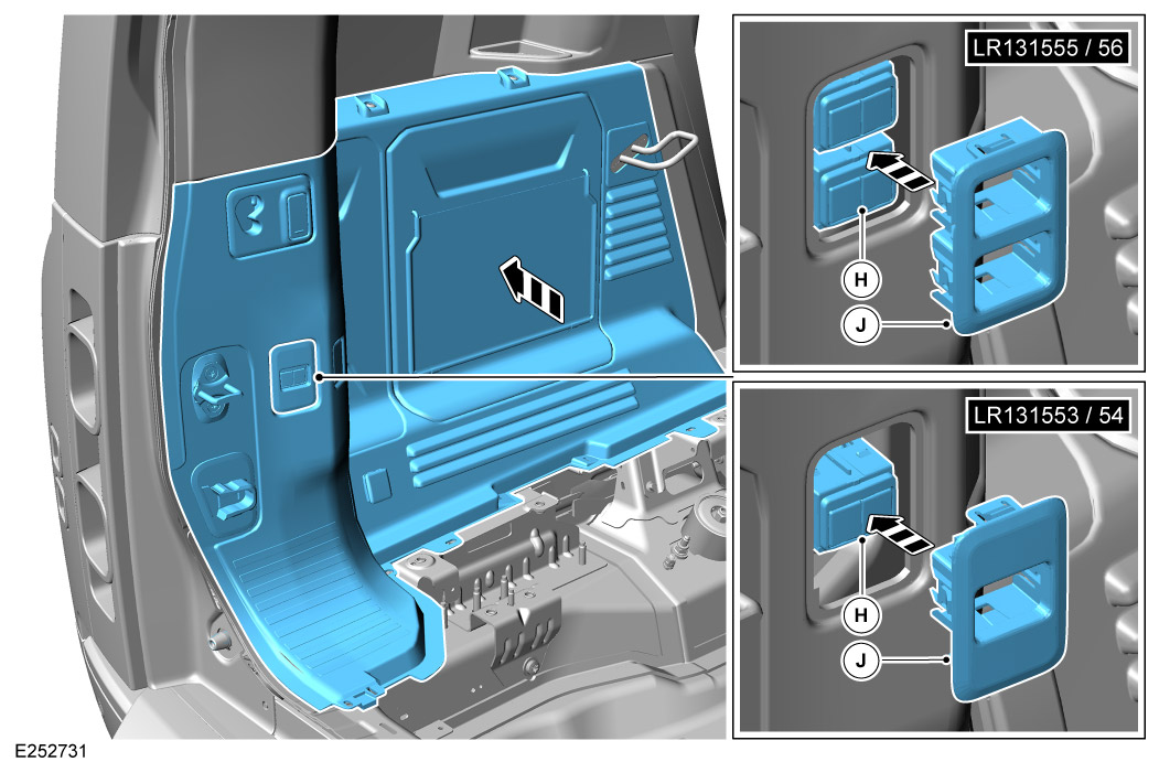
Offer up the 'Left Loadspace Trim Panel' back to the original position. Then install the switch panel (J) to the electrically deployable towbar switch (H), then install the switch panel (J) to the loadspace left trim panel.

  • After the switch is installed, then install the 'Left Loadspace Trim Panel' back the vehicle. Log into TOPIX and enter your 17 character 'Vehicle Identification Number' and navigate to 'Workshop Manual' section '501-05 Interior Trim and Ornamentation'.
61

Clip loadspace treadplate back into position and install x2 fixings.

  • Torque: 4.1Nm
62
NOTE
  • This step is 'ONLY' applicable for Defender 110.

If removed install the left C-Pillar upper trim panel.

  • Log into TOPIX and enter your 17 character 'Vehicle Identification Number' and navigate to 'Workshop Manual' section '501-05 Interior Trim and Ornamentation'.
63
NOTE
  • This step is 'ONLY' applicable for Defender 110.

If removed install cargo barrier stowage compartment.

  • Log into TOPIX and enter your 17 character 'Vehicle Identification Number' and navigate to 'Workshop Manual' section '501-05 Interior Trim and Ornamentation'.
64
NOTE
  • This step is 'ONLY' applicable for Defender 90.

If removed install x8 fixings to the front left cargo barrier side panel.

  • Torque: 6Nm
65
NOTE
  • This step is 'ONLY' applicable for Defender 90.

If removed install x6 fixings to the rear left cargo barrier side panel.

  • Torque: 6Nm
66
NOTE
  • This step is 'ONLY' applicable for Defender 110.

Install left lower cover.

  • x2 D-Loops - Torque: 24Nm
  • x2 Fixings - Torque: 3.5Nm
67
NOTE
  • This step is 'ONLY' applicable for Defender 90.

Install left lower panel.

  • D-Loops - Torque: 24Nm
  • x7 Fixings - Torque: 3.5Nm
68
NOTE
  • This step is 'ONLY' applicable for Defender 90.

Install rubber mat.

69
NOTE
  • Defender 110 shown. Defender 90 is similar.

Install x14 fixings to the cargo barrier stowage compartment.

70
NOTE
  • Defender 110 shown. Defender 90 is similar.

Install loadspace rear trim panel.

71

Connect the 12V battery.

  • Log into TOPIX and enter your 17 character 'Vehicle Identification Number' and navigate to 'Workshop Manual' section '414-00 12V System Disconnect and Connect'.
72

Use the Jaguar Land Rover (JLR) approved diagnostic equipment.

  1. Update the towbar control module to the latest software.
  2. Configure the deployable towbar hardware to enable towing on the vehicle.
  3. To enable the new changes on the vehicle: Switch off the vehicle ignition and close all apertures. Lock the vehicle for 5 minutes.
  4. After 5 minutes unlock the vehicle and perform a hard battery reset. Start the engine and make sure the 'TOWBAR' icon is shown on the Touchscreen.
73
NOTE
  • This step applies 'ONLY' to electrically deployable towbar.

Inspect the operation of the electrically deployable towbar using the electrically deployable towbar switch in the vehicle loadspace and front console.

  • If the testing is unsuccessful repeat STEP 72.
74
NOTE
  • This step applies 'ONLY' to Detachable Towbar - (VPLET0272).

Before installing the detachable towing swan neck (LR130315 or LR130317) remove the x2 protective covers (arrowed). For the removal of the protective cap on the hitch follow these steps.

  1. Insert the key and turn clockwise to unlock the handwheel.
  2. Pull the handwheel away from the tow ball. Simultaneously turn the handwheel approximately half a turn counter-clockwise. The red lug on the handwheel must enter the green indicator scale.
  3. Then remove the protective cap and store in suitable location.
75
WARNING
  • Extreme care must be taken when maneuvering the tow ball / towbar hitch. Use two hands to safely maneuver into place and make sure that no body part is below the tow ball / towbar hitch during installation or removal. Failure to safely install the tow ball could result in serious injury or death.

For installation of tow ball / towbar hitch.

  • For installation of detachable towing swan neck see your vehicles Owner's Handbook.
  • For installation of the NAS towbar hitch to the NAS Towbar, refer to the Towbar Hitch - North American Market specific instruction (VPLEY0116 / VPLEY0117).
  • For installation of the AUS towbar hitch to the AUS Towbar, refer to the Towbar Hitch - Australian Market specific instruction (VPLEY0115 / VPLEY0118).
  • For installation of Multiheight tow ball see steps 76 to 80.
76
CAUTION
  • When installing the towball (L), always use fixings (M) and (K).
NOTE
  • Fixing plate (H) is only required if you are installing to the lowest position.

Install the towball. see steps 77-80 on correct position for upper, middle or lower positions.

77
NOTE
  • Do not use the fixing plate (H) for this position.

For using the towball in the top position. Position as shown (See step 76 'B' for installation).

  • Torque: 260Nm
78
NOTE
  • Do not use the fixing plate (H) for this position.

For using the towball in the middle position. Position as shown (See step 76 'B' for installation).

  • Torque: 260Nm
79
CAUTION
  • The torque applied to the fixings that install the drop plate (H) to the towbar must be applied to the nuts (K) and not to the internal hex on the countersunk screws (J).

For using the towball in the lowest position. Position as shown (See step 76 'A' for installation).

  • Torque: 260Nm
80
NOTE
  • Illustration is from underside of the vehicle.

Depending on vehicle variant 'A' or 'B' fasten the exhaust heatshield that is located close to the multiheight drop plate towbar brackets.

  1. Use the holes in the brackets as a guide to mark 1 or 2 points, as required, on the heatshield.
  2. Drill 1 or 2 holes in the heatshield as required. Use a 7mm drill bit.
  3. Install fixings (P), (R) and (S) as required. Torque: 10Nm
81
WARNING
  • Make sure the relevant safety warnings and cautions have been read and understood before towing a trailer.

Inspect the operation of the trailer lamps and the vehicle lamps. Both trailer and vehicle lamps must be synchronized.

82

After the towball or towbar hitch has been removed it must be stored in a safe location.

  • The detachable tow ball must be removed if it is not required for immediate use. It can be stored on the loadspace tool tray in certain variants of the vehicle. If this is not the case then the detachable tow ball must be strapped to a suitable point in the vehicle.
  • The NAS or AUS towbar hitch is supplied in a hard plastic case that can be stored in the loadspace.
  • Install the protective covers back to the towbars after the towball or towbar hitch has been removed.
83

After the towball or towbar hitch has been removed it must be stored in the loadspace.

  1. The towball can be stored in the loadspace stowage compartment.
  2. The NAS or AUS towbar hitch is supplied in a hard plastic case that can be stored in the loadspace.
84

Fold up the second row seats.

85
WARNING

Motor Vehicle Data Sheets.

Motor vehicle data, Deployable Towbar Specifications
Type Coil: 6354, Air: 5802
D-value Coil / Air: 16.9 kN
Vertical coupling load Coil / Air: 350kg
Coupling class Coil / Air: A50-X
Manufacturer Brink Towing Systems B.V.
Model application Defender
EC-type approval number towbar: Coil E11*55R01/07*11284*01
EC-type approval number towbar E11*55R01/07*11283*01
EC-type approval number towbar: Air Coil / Air: 3500kg
Motor vehicle data, Detachable Towbar Specifications
Type 323-162
D-value 16.6 kN
Vertical coupling load 200kg
Coupling class A50-X
Manufacturer Westfalia-Automotive GmbH
Model application Defender
EC-type approval number towbar E13*55R01/07*4605*00
Maximum trailer weight 3000kg
Motor vehicle data, NAS Towbar Specifications
Type N/A
Vertical coupling load 350kg
Coupling class N/A
Manufacturer Westfalia-Automotive GmbH
Model application Defender
EC-type approval number towbar N/A
Maximum trailer weight 3720kg
Motor vehicle data, Australian Towbar Specifications
Type N/A
Vertical coupling load 350kg
Coupling class N/A
Manufacturer Westfalia-Automotive GmbH
Model application Defender
EC-type approval number towbar N/A
Maximum trailer weight 3000kg
Multiheight Drop Plate Towbar Specifications
Type 323-167
D-value 16.8 kN
Vertical coupling load 350kg
Coupling class A50-X
Manufacturer Westfalia-Automotive GmbH
Model application Defender
EC-type approval number towbar: Coil E13*55R01/07*4606*00
EC-type approval number towbar: Air E13*55R01/07*4607*00
Maximum trailer weight Coil / Air: 3500kg
© Land Rover 2016