SELECT YOUR LANGUAGE
Disconnect the 12V battery.
Remove the loadspace floor.
Remove x2 fixings to remove the loadspace cover.
Remove the jack from loadspace stowage compartment then remove x2 clips to remove the loadspace stowage compartment.
Remove x2 fixings and pull loadspace treadplate away from its x4 clips underneath to remove.
Remove x2 fixings to slide the antenna module away from the inner rear panel, allowing access to the studs behind.
Remove third row seat cushions.
Remove both left and right side C-pillar upper trim panels.
Remove both left and right C-pillar lower panels.
Partially lift both left and right rear treadplates from its clips where arrowed. Do not remove the rear treadplates entirely.
Towbar.
Disconnect connectors from the Towbar Control Module (TBM) . Then, remove x2 fixings to remove.
Slide TBM into deployable side step bracket (I). Make sure the holes are aligned as illustrated.
Install the TBM with deployable side step bracket.
Install the RBM(A1).
Connect the towbar harness to the RBM(A1).
Install module bracket (J) to vehicle floor studs with x2 fixings (A5). Torque: 10Nm
Install the RBM(A1) to the bracket studs and fasten with the x2 fixings (A5). Torque: 5Nm
Remove bottom back panel fixing.
Familiarize yourself with the link lead (A7) prior to installation.
Install link lead (A7).
Familiarize yourself with the deployable side steps harness (A2) prior to installation.
Lay harness (A2) in the loadspace and feed connecter (AD) under the air ducting as illustrated and connect to the RBM. Then cable tie (A10) harness (A2) to the main body harness.
Install x2 fixings to fasten the antenna module back to the inner back panel.
Continue to fasten harness (A2) with x5 clips as illustrated.
Continue to fasten (AE) side of harness (A2) with x6 cable ties (A10) as illustrated.
Lift up carpet to gain access to grommet.
Feed harness (A2) end connector (AF) through hole and fasten with grommet (AE) as illustrated. This will leave connector (AF) poking out from underneath the vehicle.
Install carpet back to its original position.
Fasten (AG) side of harness (A2) with x6 clips as illustrated in the loadspace.
Continue to fasten (AG) side of harness (A2) with x3 clips as illustrated.
Continue to fasten (AG) side of harness (A2) with x4 cable ties (A10) as illustrated.
Feed harness (A2) end connector (AH) through hole and fasten with grommet (AG) as illustrated. This will leave connector (AH) poking out from underneath the vehicle.
Locate the junction box cover in the rear right of the vehicle.
Raise and support the vehicle on a suitable 4 post lift. The front and rear subframe jacking points must be used. Do not use the sill jacking points.
Remove front fender mountings on both sides of the vehicle. Make sure care is taken when removing part, fragile retention tabs
Remove rocker panel on both sides of the vehicle.
Remove transmission shield and side undershields.
Remove x3 fixings to remove the right side undershield bracket.
Complete the following modifications the left side rocker panel only.
Complete the following modifications the right side rocker panel only.
Complete the following modifications to the left and right side undershield.
Mark and drill both left and right modified side undershields.
Drill holes at the marked locations on both left and right modified undershields using a 5mm drill bit.
Install parts (B1) and (B2).
Modify the transmission undershield.
Drill the transmission undershield extensions.
Install transmission undershield extensions.
Remove and discard the transmission support bar fixing, as illustrated, on both sides of the vehicle.
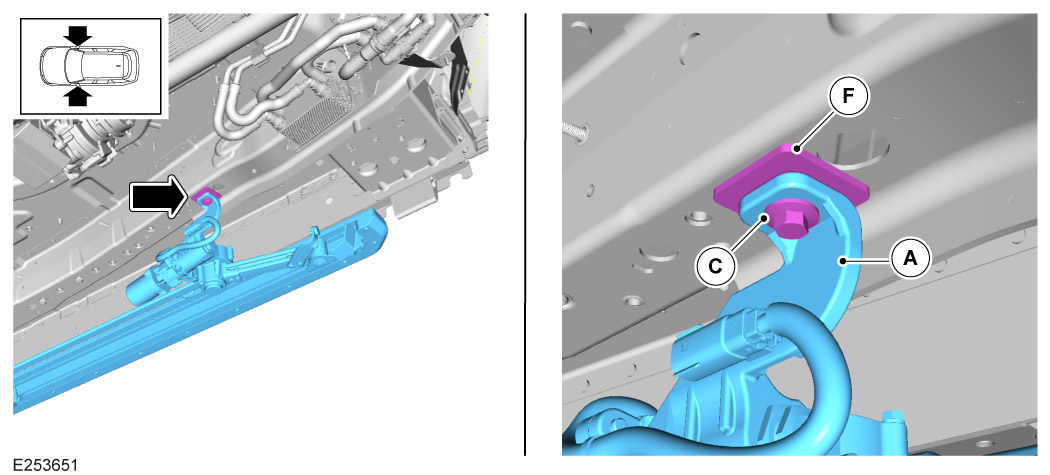
Install the deployable side step (A) using x4 fixings (B) on both sides of the vehicle. However, do not fully tighten the fixings.
Install, but do not fully tighten fixing (C) on both sides of the vehicle.
Install spacer (F) and fasten with fixing (C), but do not fully tighten, on both sides of the vehicle.
Place the x2 nut plates (D) as illustrated.
Install, but do not fully tighten, fixings (C) and the x2 washers (E) into the x2 nut plates (D).
Install, but do not fully tighten, fixing (G).
Fully tighten the x4 fixings (B) on both sides of the vehicle in the following sequence:
Fully tighten the x2 fixings (C). Torque: 29Nm
Fully tighten the fixing (C) on both sides of the vehicle. Torque: 29Nm
Fully tighten the fixing (G). Torque: 65Nm
Remove the x2 fixings and the geometry bar on both side steps.
Use the arrowed clip and the retaining clip (A9) to fasten the wiring harness (A2) to the right side of the vehicle and the body harness, as illustrated.
Use the arrowed clip and the retaining clips (A8) and (A9) to fasten the wiring harness (A2) to the left side of the vehicle and the body harness, as illustrated.
Familiarize yourself with harness (A3) and (A4) prior to installation.
For the left side of the vehicle connect the electrical wiring harness (A3) to the wiring harness (A2) with connector (AF) and to the deployable side step motor with connector (AI).
Connect the electrical wiring harness (A4) to the wiring harness (A2) with connector (AH) and to the deployable side step motor with connector (AJ).
Lower vehicle on ramp.
Connect the 12V battery.
Use the JLR approved diagnostic equipment to navigate to 'Diagnostics' section and follow the steps below.
Fully deploy the deployable side steps.
Fully disconnect and remove the electrical wiring harness (A3) and (A4) as this will now be installed to the undershields.
Raise vehicle on ramp.
Install x3 fixings to install the right side undershield bracket. Torque: 10Nm
Install the electrical wiring harness (A3) by clamping it to the left side undershield as illustrated. Repeat step for the right side undershield using the electrical wiring harness (A4).
Position the modified left undershield as illustrated and connect the electrical wiring harness (A3).
Position the modified right undershield as illustrated and connect the electrical wiring harness (A4).
Install x7 fixings (B6).
Install the rocker panel on both sides of the vehicle.
Install front fender mountings on both sides of the vehicle.
Push down both left and right rear treadplates to clip back to its original position.
Install both left and right C-Pillar Lower Trim panels.
Install both left and right side C-pillar upper trim panels.
Install third row seat cushions.
Install x2 clips to install the loadspace stowage compartment and return jack back to its position.
Install x2 fixings to install the loadspace cover.
Install the loadspace floor.
Connect the 12V battery. Make sure the deployable side steps are operating correctly and are activated for the customer handover.