LAND ROVER ACCESSORY FITTING INSTRUCTIONS

VEHICLE :
PART NO :
KEYWORD :

LAND ROVER

DEFENDER

REMOTE CONTROL ELECTRIC WINCH - V8

VPLEP0426 / LR146988 / LR146872

FITTING INSTRUCTION

WARNING
  • Accessories which are not correctly installed can be dangerous. Read the instructions carefully prior to installation. Comply with instructions at all times. If in doubt, contact your nearest approved retailer.
Accessory Part Number
Remote Control Electric Winch VPLEP0426

Remote Control Electric Winch (Bill of Materials) - VPLEP0426

NOTE
  • Not all clips and cable ties are used in the following procedure.

Additional clips that must be ordered (Bill of Materials) - LR146872 / LR146986

Wireless Remote.

NOTE
  • Make sure the wireless remote (D1) is fully charged.

Warnings / Cautions / Notes

WARNING
  • You must wear suitable personal protective equipment when cutting / drilling parts.
CAUTION
  • Due to the nature of this accessory it is recommended for retailer installation only. If a customer attempts to install this accessory themselves they will require a copy of the workshop manual links within this procedure.
  • Do not attempt to repair any part of a wiring harness unless appropriate training has been received.
  • When installing the leads avoid trapping the leads and route the leads away from any sharp objects.
NOTE
  • Before you can install the 'Remote Control Electric Winch' you have to first install the 'Winch Mounting Kit' VPLEP0427 / VPLEP0490 or the 'Bull Bar Mounting Kit' VPLEP0449 / VPLEP0489.
  • For winch Operational Manuals, Instructions, Quick Start Guide, Synthetic Rope Installation Guide etc, go to https://international.warn.com and navigate to 'Zeon 10-S Platinum Winch' where the documentation can be found under the ‘Manuals and Literature’ section.
  • Paid subscription to TOPIX required to view workshop manual links.
Fitting Instruction
1

To install the 'Remote Control Winch' you will first must install one of the following.

  1. If you intend to just have the 'Remote Control Electric Winch' installed then first look at instruction 'Winch Mounting Kit' accessory instructions.
  2. If you intend to have the 'Remote Control Electric Winch' with 'Bull Bar' installed then first look at instruction 'Bull Bar Mounting Kit' accessory instructions.
2

If not already done so, disconnect the 12V battery.

  • Log into TOPIX and enter your 17 character 'Vehicle Identification Number' and navigate to 'Workshop Manual' section '414-00 12V System Disconnect and Connect'.
3
NOTE
  • The orientation of the hexagonal sealing connector (B1) must be moved flush with the mounting plate to clear the screw head.
  • To aid installation hand start the screws (N) and hook the relay module box (B) over screws before tightening.

Use x2 fixings (N) to install the relay module box (B) to the winch cradle. Torque: 4Nm

4
CAUTION
  • Failure to fasten the leads risk contact with the vehicle air conditioning fan unit.

Fasten positive winch lead (A1).

  1. Remove the screw from the winch.
  2. Fasten the P-clip (U) to the positive winch lead (A1) and install on the winch body where illustrated with the removed screw. Torque: 7Nm
5

Install large diameter convoluting (J1).

  1. Install large diameter convoluting (J1) to the full length of lead (A1), starting from the P-clip (U). Feeding convolute through any grommets.
  2. Install large diameter convoluting (J1) to the full length of lead (A2). Feeding convolute through any grommets.
6
CAUTION
  • Avoid trapping the harness and route the harness away from any sharp objects.
NOTE
  • The aid of a second technician is necessary.
  • Movement of the winch unit may be necessary for access.

Lower the winch (A) into the winch cradle.

7

Connect relay module lead to winch.

  1. Located at the bottom of the winch remove the negative (-) fixing and measure. If the fixing is below 16mm then replace fixing with the M8 x 16mm (-) fixing supplied loose in the remote control electric winch kit.
  2. Fasten the relay module ground lead from (B1) to the negative lead attachment. Torque: 12Nm
  3. Connect the (B1) connector to connector (A3) as shown..
8

Use x5 Cable ties (O) and fasten where shown.

9
NOTE
  • If the arrowed hole is not present in the winch upper ducting, make a 30mm hole approximately 50mm from the edge of the upper ducting as shown.

Route winch power lead.

  1. Feed both the winch power lead (A1) and convoluting through the winch upper ducting (D) and fasten the grommet.
  2. Then, feed (A1) through the overload interrupt unit (C).
10
NOTE
  • This step requires the aid of another technician.
  • The winch upper ducting (D) can be found in the 'Winch Mounting Kit' or 'Bull Bar Mounting Kit'.

Lower the winch upper ducting (D) into the correct position as illustrated. Do not install the winch upper ducting (D) at this stage.

11

Feed the ground lead (A2) through the winch upper ducting (D) and fasten the grommet.

12
NOTE
  • Make note of the orientation of (C).

Install the overload interrupt unit (C) to mounting cradle with x2 fixings (M) and (R).

13

Remove right side air filter and headlamp assembley.

  • Log into TOPIX and enter your 17 character 'Vehicle Identification Number' and navigate to 'Workshop Manual' section '303-12D Intake Air Distribution and Filtering'.
  • Log into TOPIX and enter your 17 character 'Vehicle Identification Number' and navigate to 'Workshop Manual' section '417-02 Exterior Lighting'.
14
NOTE
  • Do not fully tighten cable ties as other leads will be fed through when required.

Feed both leads (A1) and (A2) through the vehicle body as shown and fasten with clips (H) and (I).

  1. For clip (H) a 6.9mm hole must be drilled into the air duct cover if not already present.
  2. Install clip (I) as shown, then cable tie the clip to leads (A2) and (B1).
15
NOTE
  • Do not fully tighten cable ties as other leads will be fed through when required.

Fasten clip (H) to the winch cradle and clip (G) to the vehicle frame.

16
CAUTION
  • Avoid trapping ground lead (A2) and route the lead away from any sharp objects including nuts, bolts and moving parts. make sure a minimum clearance of 6mm is maintained to all adjacent components unless the wiring assembly is positively retained to the component.

Continue to feed the ground lead (A2) as shown and connect the end to stud on suspension mounting panel (where arrowed). Torque: 12 Nm.

  1. Fasten with x1 cable tie (O).
  2. Fasten with x1 clip (V).
  3. Fasten with x2 clips (Z1).
  4. Fasten with x2 clips (Z2).
17
CAUTION
  • Avoid trapping ground lead (A2) and route the lead away from any sharp objects including nuts, bolts and moving parts. make sure a minimum clearance of 6mm is maintained to all adjacent components unless the wiring assembly is positively retained to the component.

Install cable tie (O) where shown to existing body harness.

18
NOTE
  • Do not fully tighten cable ties as other leads will be fed through when required.

Feed winch power led (A1) as shown.

  1. Remove harness housing box cover.
  2. Continue to feed winch power lead (A1) as shown and loosely cable tie (O) to the body harness. Convolute must stop before the harness housing box and continue on the other side.
  3. Feed the winch power lead (A1) along the body harness to the rear of the positive terminal box and remove the terminal cover.
  4. Cable tie on the far right can be fully tightened.
19
NOTE
  • Depending on which fuse locations are used, either side of the terminal cover sections may be removable.

Fuse installation.

  1. Cut out the highlighted section (yellow) of the terminal cover.
  2. Install the fuse (F) and winch power lead (A1) to terminal C6 using x2 fixings (Q). Torque: 12Nm
  3. Install the terminal cover.
20
NOTE
  • Do not fully tighten cable ties as other leads will be fed through when required.
  • When connected, the surplus antenna lead can be bundled next to the antenna pod.

Install antenna lead (E).

  1. Peel off the protective adhesive cover from underneath of the antenna pod and stick it on top of the positive terminal cover.
  2. Feed the antenna lead through any loose cable ties, following the same route as winch power lead (A1) to the front of the vehicle.
21

Continue to route the antenna lead (E) as shown, passing it through any loose cable ties indicated by arrows.

22

Fasten antenna lead (E).

  1. Feed lead (E) through the overload interrupt unit power lead grommet.
  2. Install leads (A4) and (E) using clip (H) into the winch upper ducting, and fasten with cable tie (O), as shown.
23
CAUTION
  • Failure to fasten the leads risk contact with the vehicle air conditioning fan unit.

Connect the antenna lead (E).

  1. Connect lead (E) coaxial connector to the coaxial connector on the rear of the winch unit (A5).
  2. Fasten the connection using a cable tie (O).
24

Connect lead (A4) to the overload interrupt unit.

25

Feed lead (B1) to front of vehicle.

  1. Feed lead (B1) and in-line connector through the upper winch ducting, securing the grommet.
  2. Fasten the connector to the vehicle body using clip (X).
  3. Fasten with x4 cable ties (O).
26

Install lead (K) connector to the in-line lead (B1) connector and fasten with x3 cable ties (O).

27

Remove the cowl panel.

  • Log into TOPIX and enter your 17 character 'Vehicle Identification Number' and navigate to 'Workshop Manual' section '501-02 Front End Body Panels.
28

Route lead (K).

  1. Route lead (K) through the harness housing box.
  2. Pass lead through any loose cable ties.
  3. Continue routing lead through the hole in the secondary bulkhead panel.
  4. If necessary, drill a 5mm hole in the secondary bulkhead panel at the indicated position.
  5. Make sure that the convolute stops before reaching the harness housing box and continues on the other side.
29
NOTE
  • right hand drive (RHD) vehicles 'ONLY'.

Route lead (K) lead up to the junction box as shown. The lead will be tied to the cowl panel on installation.

30

Release the x4 clips and remove the Engine Junction Box (EJB) cover.

31
NOTE
  • left hand drive (LHD) vehicles 'ONLY'.

Install the black and red wires from lead (K) into the EJB connectors.

  1. Remove all 4 connectors and harness grommets for easy access.
  2. Remove connector covers on connectors 'C1BB03A' and 'C1BB06B'
  3. Pull out anti-backout lock on connectors 'C1BB03A' and 'C1BB06B', taking care to remove the anti-backout lock fully.
  4. Take note of the pin locations in the illustration prior installation and check to see if any splicing of wires is required (If splicing wires is required see Step 34)..
  5. Install the black and red wires from lead (K) into its relevant pin on the connector. Then push back in the anti-backout lock on the connector.
32
NOTE
  • RHD vehicles 'ONLY'.

Install the black and red wires from lead (K) into the EJB connectors.

  1. Remove all 4 connectors and harness grommets for easy access.
  2. Remove connector covers on connectors 'C1BB03A' and 'C1BB06B'
  3. Pull out anti-backout lock on connectors 'C1BB03A' and 'C1BB06B', taking care to remove the anti-backout lock fully.
  4. Take note of the pin locations in the illustration prior installation and check to see if any splicing of wires is required (If splicing wires is required see Step 34).
  5. Install the black and red wires from lead (K) into its relevant pin on the connector. Then push back in the anti-backout lock on the connector.
33
NOTE
  • This step is 'ONLY' for splicing wires if required.

If splicing maybe required.

  1. Log into TOPIX and enter your 17 character 'Vehicle Identification Number' and navigate to 'Workshop Manual' section '418-02 Wiring Harness'
  2. Cut and strip the existing wire from pin 16 on connector 'C1BB03A' and use splice (S1) to splice together the existing wire and the black wire from lead (K).
  3. Use heat shrink (S2) to seal splice.
  4. Install the red wire from lead (K) into pin 10 on connector 'C1BB06A'. Then push back in the anti-backout lock.
34
CAUTION
  • Failure to correctly seal the EJB grommets will result in serious damage to the vehicles electrical system.

Install all x4 EJB harness connectors and harness grommets back to there original locations.

35
CAUTION
  • Failure to correctly seal the EJB grommets will result in serious damage to the vehicles electrical system.

Allow lead (K) access into the EJB.

  1. Cut a small indent into the grommet the same width as lead (K).
  2. Lay lead (K) into the indent you have just cut.
  3. Seal with putty to create a weather proof seal.
36

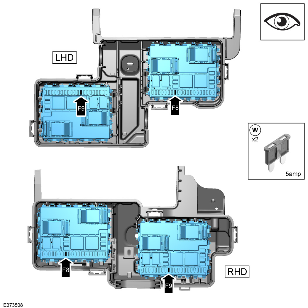
Check if a 5amp micro fuse are populated in the positions shown. If micro fuses are not present, install the micro fuse (W) into the vacant slots.

37

Install the EJB cover. Then tighten all cable ties and clips throughout the whole procedure before testing the winch.

38

Fasten lead (K).

  1. Install harness housing box cover.
  2. For left hand vehicles LHD only, bundle up excess lead as shown. Fasten with x2 cable ties (O).
  3. Fully tighten x5 cable ties (O).
  4. Then tighten all cable ties and clips throughout the whole procedure before testing the winch. Failure to fasten all cable ties correctly will result in damage to the component.
39

Install right side air filter and headlamp assembley.

  • Log into TOPIX and enter your 17 character 'Vehicle Identification Number' and navigate to 'Workshop Manual' section '303-12D Intake Air Distribution and Filtering'.
  • Log into TOPIX and enter your 17 character 'Vehicle Identification Number' and navigate to 'Workshop Manual' section '417-02 Exterior Lighting'.
40

Connect the 12V battery and turn on ignition to provide power to the winch.

  • Log into TOPIX and enter your 17 character 'Vehicle Identification Number' and navigate to 'Workshop Manual' section '414-00 12V System Disconnect and Connect'.
41
NOTE
  • The winch switch must be in the on position.
  • For more information refer to the Warn winch instructions in the kit.

Turn on the winch. The toggle switch at the rear of the winch will flash green when switched on.

42
CAUTION
  • Never pair more than one winch and one remote at a time.
NOTE
  • For more information refer to the Warn winch instructions in the kit.

To pair the remote (D1) make sure the vehicle ignition is switched off and fully shut down, then follow these steps:

  1. Navigate to the pairing icon and press select.
  2. Press and hold select and the right button simultaneously for 3 seconds to bring up the pairing confirmation menu.
43
NOTE
  • Print off steps 42 and 43 and put in winch operating guide for future pairing if required.

Continue pairing.

  1. To continue pairing, select the green check mark icon by navigating with the left or right buttons and press select.
  2. After selecting the green check mark icon, a timer will begin counting down from 30 seconds.
  3. During the 30 seconds, turn the vehicle ignition on (without starting the engine).
  4. The winch must now be paired. If unsuccessful (red cross will show), turn the vehicle ignition off. The vehicle must fully shut down, check the alarm is on and lights have turned off. Now restart the pairing process from step 42.
44
NOTE
  • Refer to Warn winch manual for instructions.
  • When the engine is cranked, lead (K) will give a voltage spike of approximately 12V.

Test the remote control electric winch is working correctly.

  1. Turn on the vehicle ignition.
  2. Test the operation of the remote control electric winch.
  3. If the winch does not operate:
    1. • Make sure that the winch connectors are correctly inserted.
    2. • Verify that lead (K) are receiving 12v.
    3. • For more information, refer to the electrical wiring diagrams in the 'Electrical Information' section of TOPIX.
45
NOTE
  • RHD vehicles 'ONLY'.

Cable tie lead (K) where shown to any existing wires.

46

Install the cowl panel. For RHD vehicles install the cowl panel back into position and cable tie lead (K) to cowl panel.

  • Then install the cowl panel back to the vehicle. Log into TOPIX and enter your 17 character 'Vehicle Identification Number' and navigate to 'Workshop Manual' section '501-02 Front End Body Panels.
47

Install winch to mounting cradle .

  1. Move the winch over the securing holes on the cradle.
  2. Install the winch to the cradle using fixings (L) and (P). Torque: 40Nm
  3. Install feed pin (T). See next step.
48

Attach the rope lanyard.

  1. Manoeuver the rope lanyard through the cradle as illustrated.
  2. Feed pin (T) through the gap between the thimble and rope.
  3. Make sure pin and clip remain attached to rope end.
49

Install the winch upper ducting using the x4 fixings (H1) from the winch mounting kit or bull bar mounting kit. Torque: 10Nm

50

Store the following items in the vehicle's glove box:

  • Winch instructions.
  • Remote control (D1).
  • Charger lead.
  • Charger adapter.
  • Wear sleeve and hook etc.
51

Continue to follow instructions for either:

  • Winch Mounting Kit: Refer to Section 102-05 Towing, 'Winch Mounting Kit' installation instructions.
  • Bull Bar Mounting Kit: Refer to Section 102-03 Exterior, 'Bull Bar Mounting Kit' installation instructions.
© Land Rover 2016