LAND ROVER ACCESSORY FITTING INSTRUCTIONS

VEHICLE :
PART NO :
KEYWORD :

LAND ROVER

DEFENDER

DEPLOYABLE SIDE STEPS - 110 COMMERCIAL

VPLEP0393 / VPLEP0394 / VPLEP0422 / VPLEV0129 / VPLLE0054 / VPLLE0055

FITTING INSTRUCTION

WARNING
  • Accessories which are not correctly installed can be dangerous. Read the instructions carefully prior to ordering and installation to make sure this accessory is applicable to your variant of vehicle. Comply with instructions at all times. If in doubt, contact your nearest approved retailer.
Kits Required Part Number Superseded by
Deployable Side Step - Right Side VPLEP0393 VPLLE0054
Deployable Side Step - Left Side VPLEP0394 VPLLE0055
Undershields VPLEP0422
Deployable Side Step - Harness VPLEV0129
Running Board Control Module (RBM) VPLET0278
Trim Clips (Ordered as required) LR112137

Deployable Side Steps (Bill of Materials)

Undershields (Bill of Materials)

Deployable Side Steps Harness and RBM (Bill of Materials)

NOTE
  • The module (VPLET0278) must be used as this has the deployable side step functionality. The module (VPLET0278) must be ordered if the vehicle is not already equipped with a module of type VPLET0278. The towing module (LR129345) does not include the deployable side step functionality.

Trim Clips

NOTE
  • Trim clips - LR112137 must be ordered as required if they are damaged during removal of the exterior body trims. The maximum quantity that may be required is x30 for both sides of the vehicle.

Warnings / Cautions / Notes

WARNING
  • Make sure to wear suitable personal protective equipment when cutting / drilling parts.
CAUTION
  • Make sure all electrical wiring harness avoid any sharp edges when installed.
  • Do not loosen any fixings on the deployable side steps prior to installation.
NOTE
  • Place the vehicle on a 4 post ramp before installation.
  • This procedure contains some variation in the illustrations depending on the vehicle specification, but the essential information is always correct.
  • This procedure contains illustrations for left side components, right side components are similar.
  • Paid subscription to TOPIX required to view workshop manual links.
Fitting Instruction
1

Disconnect the 12V battery.

  • Log into TOPIX and enter your 17 character 'Vehicle Identification Number' and navigate to 'Workshop Manual' section '414-00 12V System Disconnect and Connect'.
2

Remove the rear loadspace floor panel.

3

Remove the rear loadspace floor storage tray.

4
NOTE
  • The 4 side fixings shown are hidden behind the top of stowage door surround.

Remove the front loadspace floor panel.

5

Remove the stowage door surrounds.

6
NOTE
  • Disconnect the two light connectors before completely removing the tray.

Remove the front loadspace floor storage tray.

7

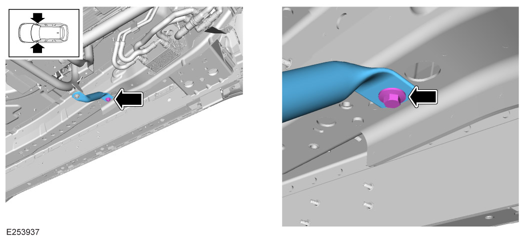
Remove the blanking grommet to the rear of the rear treadplate trims.

8
NOTE
  • The link lead (A7) must be installed if the vehicle is not already equipped with towing. Vehicles with towing installed will already have this link lead installed to the vehicle.

Place the module (A1) into the loadspace at the correct location, but do not fasten at this stage.

  1. Connect the electrical wiring harness (A2) and the link lead (A7) to the module.
  2. Connect the clip, part of the electrical wiring harness (A2), to the vehicle body as illustrated. If the vehicle is already equipped with a towing system then the clip cannot be used because the towing harness will already be using the clip connection location on the vehicle body.
  3. Use the tie wraps (A10) to fasten the electrical wiring harness (A2) to the body wiring harness as illustrated.
9
NOTE
  • The electrical wiring harness connectors will already be connected to the module. Harness hidden in illustration to provide extra clarity.
  • This step must be completed if the vehicle is not already equipped with a module of type VPLET0278.
  • This step must be completed if the vehicle is equipped with the module (LR129345) which must be removed and replaced with the module (VPLET0278). The module (VPLET0278) has 4 connectors.
  • Install the speaker only if the electrically deployable towbar is also being installed. The speaker is not required for the deployable side steps to operate correctly.

Install the RBM(A1) using the x2 fixings (A5). Install the speaker only if required. Torque: 5Nm

10
NOTE
  • Complete step on both sides of the vehicle.

Grommet access.

  1. Remove the carpet retaining clip from the area of carpet under the second row seats. Move the carpet aside to gain access to the core harness conduit.
  2. Release x2 M6 fixings to allow access to the grommet underneath.
11

Continue to fasten the electrical wiring harness (A2).

  1. Install the 2 retaining clips, part of the electrical wiring harness (A2) to the vehicle body.
  2. Use the tie wraps (A10) to fasten the wiring harness to the core harness conduit as illustrated.
  3. Install the retaining clip. Release the vehicle body fixing first, install the retaining clip and then tighten the fixing.
  4. Feed the wiring harness through the floor.
  5. Install the grommet. Make sure the grommet is correctly installed.
  6. Install the x2 M6 fixings to fasten the core harness conduit under the treadplate.
12

Continue to fasten the electrical wiring harness (A2).

  1. Use the x3 retaining clips, part of the to electrical wiring harness, to fasten the harness to the rear cross member.
  2. Use 2 tie wraps (A10) to fasten the harness to the rear cross member.
13

Continue to fasten the electrical wiring harness (A2).

  1. Use the tie wraps (A10) to fasten the wiring harness to the core harness conduit as illustrated.
  2. Install the retaining clip. Release the vehicle body fixing first, install the retaining clip and then tighten the fixing.
  3. Feed the wiring harness through the floor.
  4. Install the grommet. Make sure the grommet is correctly installed.
  5. Install the x2 M6 fixings to fasten the core harness conduit under the treadplate.
14
CAUTION
  • Make sure to use the front and rear subframe jacking points.
NOTE
  • Make sure the ramp legs are positioned so they do not obstruct the deployable side step installation locations.

Raise and support the vehicle on a suitable 4 post lift. The front and rear subframe jacking points must be used. Do not use the sill jacking points.

  • Log into TOPIX and enter your 17 character 'Vehicle Identification Number' and navigate to 'Workshop Manual' section '100-02 Jacking and Lifting'.
15
CAUTION
  • Make sure that the x4 clips remain on the front fender moulding when removed. Replace clips if they are damaged.
NOTE
  • Remove the front mudflaps if installed to the vehicle.

Remove front fender mountings on both sides of the vehicle.

  • Log into TOPIX and enter your 17 character 'Vehicle Identification Number' and navigate to 'Workshop Manual' section '501-08 Exterior Trim and Ornamentation'.
16
CAUTION
  • Replace clips if damaged.

Remove rocker panel on both sides of the vehicle.

  • Log into TOPIX and enter your 17 character 'Vehicle Identification Number' and navigate to 'Workshop Manual' section '501-08 Exterior Trim and Ornamentation'.
17

Remove transmission and side undershields.

  • Log into TOPIX and enter your 17 character 'Vehicle Identification Number' and navigate to 'Workshop Manual' section '501-02 Front End Body Panels'.
18

Use suitable tooling to cut the illustrated sections from the removed left side rocker panel. Discard the removed sections.

  1. Identify the cut guide lines. Paint over the cut guide lines to make the cut guide lines clearer.
  2. Drill holes at the illustrated locations.
  3. Use the cut guide lines on the rocker panel.
19

Use suitable tooling to cut the illustrated sections from the removed right side rocker panel. Discard the removed sections.

  1. Identify the cut guide lines. Paint over the cut guide lines to make the cut guide lines clearer.
  2. Drill holes at the illustrated locations.
  3. Use the cut guide lines on the rocker panel.
20
CAUTION
  • There are multiple cut guide lines on the surface of the undershield. Make sure the correct cut guide lines are followed as illustrated.
NOTE
  • Left side shown. Right side similar.

Cut both removed side undershields.

  1. Identify the cut guide line on the undershield as illustrated. Paint over the cut guide lines to make the cut guide lines clearer.
  2. Use suitable tooling to cut the illustrated sections from the undershield. Discard the removed section.
21
WARNING
  • Make sure to wear suitable personal protective equipment.
NOTE
  • Left side undershield shown. Undershield illustrated in correct installation position on vehicle and viewed from above.

Use suitable tooling to cut the illustrated sections from the undershield. Discard the removed section.

22
NOTE
  • Left side shown. Right side similar.

Locate part (B1) against the left side undershield as illustrated. Part (B2) is used for the right side undershield.

  1. Use the guide holes provided on the part (B1 or B2) to carefully mark the undershield.
  2. Remove part .
23
NOTE
  • Left side shown. Right side similar.

Drill holes using a 5mm drill bit at the marked locations on both left and right undershields.

24
NOTE
  • Left side shown. Right side similar.

Using the x12 rivets (B10) and the x12 washers (B9), install the part (B1 or B2) to the left and right undershields as illustrated.

25
NOTE
  • Left side undershield shown, viewed from below the vehicle. Undershield illustrated in correct installation position on vehicle and viewed from below.
  • When viewed from below, the part (B1) is located above the left side undershield.

Make sure the part (B1) is correctly installed to the left side undershield.

26
WARNING
  • Make sure to wear suitable personal protective equipment.
CAUTION
  • The foil heatshield is riveted to the core material transmission undershield. The rivets must be drilled out.

Cut the removed transmission undershield.

  1. Identify the cut guide lines on the undershield as illustrated. Paint over the cut guide lines to make the cut guide lines clearer.
  2. Use suitable tooling to cut the illustrated sections from the undershield. Discard the removed sections.
27
WARNING
  • Make sure to wear suitable personal protective equipment.
NOTE
  • Drill out the rivet in the foil heatshield.

Offer up the transmission undershield extension parts (B3) and (B4) against the transmission undershield as illustrated.

  1. Use the guide holes provided on the transmission undershield extension parts to mark the undershield.
  2. Remove both transmission undershield extension parts and drill holes at the marked locations on the transmission undershield using a 5mm drill bit.
28

Using the x12 rivets (B10) and the x12 washers (B9), install both transmission undershield extension parts to the transmission undershield as illustrated.

  • The foil heatshield is installed again using the deployable side step plastic undershield rivet.
29
CAUTION
  • Diesel vehicles 'ONLY'.

Remove and discard the transmission support bar fixing bolt, as illustrated, on both sides of the vehicle.

30
CAUTION
  • Install, but do not fully tighten the fixings.
  • Do not remove the deployable side step boards from the brackets.
  • Do not remove the calibration bar on the deployable side step.
NOTE
  • This step requires the aid of another technician.

Install the deployable side step (A) using x4 fixings (B) on both sides of the vehicle.

31
CAUTION
  • Diesel vehicles 'ONLY'.

Install, but do not fully tighten fixing (C) on both sides of the vehicle.

32
CAUTION
  • Non-diesel vehicles 'ONLY'.

Install spacer (F) and install, but do not fully tighten fixing (C) on both sides of the vehicle.

33
NOTE
  • Complete step on left side of vehicle 'ONLY'.

Install x2 nut plates (D) as illustrated.

34

Install, but do not fully tighten the fixings (C) and washers (E) on both sides of the vehicle.

35
NOTE
  • Complete step on right side of vehicle 'ONLY'.

Install, but do not fully tighten the fixing (G).

36

Fully tighten fixings (B) in the sequence shown on both sides of the vehicle. Torque: 29Nm

37
NOTE
  • Complete step on left side of vehicle 'ONLY'.

Fully tighten fixings (C). Torque: 29Nm

38

Fully tighten fixings (C) on both sides of the vehicle. Torque: 29Nm

39
NOTE
  • Complete step on right side of vehicle 'ONLY'.

Fully tighten fixing (G). Torque: 65Nm

40

Remove the x2 fixings and the geometry bar on both side steps.

41

Use the arrowed clip and the arrowed retaining clip (A9) to fasten the wiring harness (A2) to the right side of the vehicle and the body harness as illustrated.

42

Use the arrowed clip and the arrowed retaining clip (A8) to fasten the wiring harness (A2) to the left side of the vehicle and the body harness as illustrated.

43

To test the operation of the deployable side steps before complete installation, connect the electrical wiring harness (A2) to both deployable side step motors.

  • Connect the link lead (A3) that is installed to the left side of the vehicle has yellow color tape.
  • Connect the link lead (A4) that is installed to the right side of the vehicle has blue color tape.
44

Lower vehicle on ramp.

45

Connect the 12V battery.

  • Log into TOPIX and enter your 17 character 'Vehicle Identification Number' and navigate to 'Workshop Manual' section '414-00 12V System Disconnect and Connect'.
46

Using the Jaguar Land Rover approved diagnostic equipment update the module to the latest level. Then enable the deployable side steps on the vehicle. After the deployable side steps have been enabled using the diagnostic equipment, then go into the deployable side step menu on the front screen and enable the side steps. The default is that the deployable side steps will be disabled. To enable the new changes to the vehicle, follow the steps below.

  1. Switch off the vehicle ignition, close all apertures. Lock the vehicle for 5 minutes.
  2. After 5 minutes unlock the vehicle and perform a Pivi reset by pressing the infotainment power on/volume button for 20 seconds.
  3. Start the engine and make sure the 'SIDE STEPS' icon is shown on the touchscreen.
47
NOTE
  • This step is required to install the side undershields and rocker panels.

Fully deploy the deployable side steps.

  • Make sure the deployable side steps are operating correctly when opening and closing the doors on both sides of the vehicle.
48
CAUTION
  • Make sure the vehicle ignition is off.
  • Disconnect the startup battery terminal before disconnecting the harness from the motor. Complete task while the steps are still in the fully deployed position.

Fully disconnect and remove the electrical wiring harness (A3) and (A4) as this will now be installed to the undershields.

  • Log into TOPIX and enter your 17 character 'Vehicle Identification Number' and navigate to 'Workshop Manual' section '414-00 12V System Disconnect and Connect'.
49

Raise vehicle on ramp.

50
NOTE
  • Make sure that the correct link lead is installed.

Install the electrical wiring harness (A3) by clamping it to the left side undershield as illustrated. Repeat step for the right side undershield using the electrical wiring harness (A4).

51
NOTE
  • This step requires the aid of another technician.

Offer up the left side undershield as illustrated and connect the electrical wiring harness (A3).

  1. Connect the electrical wiring harness (A3) to the wiring harness (A2) and one end and the deployable side step motor at the other end.
  2. Use the clip (A9) to fasten the harness to the deployable side step motor cable.
  3. Install the left undershield. Log into TOPIX and enter your 17 character 'Vehicle Identification Number' and navigate to 'Workshop Manual' section '501-02 Front End Body Panels'.
52
NOTE
  • This step requires the aid of another technician.

Offer up the right side undershield and connect the electrical wiring harness (A4).

  1. Connect the electrical wiring harness (A4) to the wiring harness (A2) and one end and the deployable side step motor at the other end.
  2. Use the clip (A9) to fasten the harness to the deployable side step motor cable.
  3. Install the left undershield. Log into TOPIX and enter your 17 character 'Vehicle Identification Number' and navigate to 'Workshop Manual' section '501-02 Front End Body Panels'.
  4. Install the transmission undershield. Log into TOPIX and enter your 17 character 'Vehicle Identification Number' and navigate to 'Workshop Manual' section '501-02 Front End Body Panels'.
53
NOTE
  • Make sure side steps are deployed before you can install fixings.

Install x7 fixings (B6).

54

Lower vehicle on ramp.

55

Re-install parts in this order on both sides of the vehicle. Log into TOPIX and enter your 17 character 'Vehicle Identification Number' and navigate to 'Workshop Manual' sections.

  1. Rocker Panel '501-08 Exterior Trim and Ornamentation'
  2. Front Fender Moulding '501-08 Exterior Trim and Ornamentation'
  3. Install the loadspace floor storage tray removed in step 6.
  4. Install the stowage door surrounds removed in step 5.
  5. Install the front loadspace floor panel removed in step 4.
  6. Install the rear loadspace floor storage tray removed in step 3.
  7. Install the rear loadspace floor panel removed in step 2.
56

Connect the 12V battery. Make sure the deployable side steps are operating correctly and are activated for the customer handover.

  • Log into TOPIX and enter your 17 character 'Vehicle Identification Number' and navigate to 'Workshop Manual' section '414-00 12V System Disconnect and Connect'.
© Land Rover 2016