LAND ROVER ACCESSORY FITTING INSTRUCTIONS

VEHICLE :
PART NO :
KEYWORD :

LAND ROVER

DEFENDER

BULL BAR MOUNTING KIT

VPLEP0449 / VPLEP0489 / VPLEP0431 / VPLEB0442 / LR129440

FITTING INSTRUCTION

WARNING
  • Accessories which are not correctly installed can be dangerous. Read the instructions carefully prior to ordering and installation to see if this accessory is applicable to your variant of vehicle. Comply with instructions at all times. If in doubt, contact your nearest approved retailer.
Accessories Part Number Superseded By
Bull Bar Mounting Kit - 1st Release version VPLEP0449 VPLEP0489
Bull Bar Mounting Kit - 2nd Release version VPLEP0489
Crush Cans VPLEP0431
Defender-X 'ONLY' H-Panels VPLEB0442
Defender-X 'ONLY' Grille LR129440

Bull Bar Mounting Kit (Bill of Materials) - VPLEP0449

NOTE
  • There will be 2 spare (L1) and (Q1) fixings at the end of installation on kit - VPLEP0449.
  • Parts (Q), (SS1) and (SS2) will be installed when installing the 'Bull Bar' - VPLEP0448.

Bull Bar Mounting Kit (Bill of Materials) - VPLEP0489

NOTE
  • Parts (Q), (SS1) and (SS2) will be installed when installing the 'Bull Bar' - VPLEP0448.

Crush Cans (Bill of Materials) - VPLEP0431

Bumper parts for Defender-X vehicles only (Bill of Materials) - VPLEB0442 / LR129440

Warnings / Cautions / Notes

WARNING
  • Make sure to wear suitable personal protective equipment when drilling or cutting parts.
CAUTION
  • Installation of 'Bull Bar Mounting Kit' - VPLEP0449 / VPLEP0489 to Plug-in Hybrid Electric Vehicle (PHEV) vehicles, will require the sounder link harness which is only available as part of (VPLEP0426) Remote Electric Winch kit.
  • The 'Bull Bar' - VPLEP0448 is not part of the 'Bull Bar Mounting Kit' - VPLEP0449 / VPLEP0489. This part must be ordered separately.
NOTE
  • The 'Bull Bar Mounting Kit' can be ordered with either (VPLEP0449 or VPLEP0489).
  • Paid subscription to TOPIX required to view workshop manual links.
Fitting Instruction
1
CAUTION
  • For vehicles installed with coil suspension 'ONLY'.

If the remote control electric winch is also being installed in conjunction with the bull bar, replace the front coil springs with the correct kit below listed. If not then proceed to next step.

  • 6 Cyl 90 L8BM-5B302-AA VPLEI0604.
  • 6 Cyl 110 L8BM-5B302-BA VPLEI0605.
  • 4 Cyl 90 L8B2-5C314-KA LR140233.
  • 4 Cyl 110 L8B2-5C314-EA LR140355.
  • Log into TOPIX and enter your 17 character 'Vehicle Identification Number' and navigate to 'Workshop Manual' section '204-01 Shock Absorber and Spring Assembly - Coil Suspension'.
2

Disconnect the 12V battery.

  • Log into TOPIX and enter your 17 character 'Vehicle Identification Number' and navigate to 'Workshop Manual' section '414-00 12V System Disconnect and Connect'.
3

Remove radiator grille.

  • Log into TOPIX and enter your 17 character 'Vehicle Identification Number' and navigate to 'Workshop Manual' section '501-08 Exterior Trim and Ornamentation'.
4
NOTE
  • Do not remove fog lamps if present.

Remove front bumper.

  • Log into TOPIX and enter your 17 character 'Vehicle Identification Number' and navigate to 'Workshop Manual' section '501-19 Bumpers'.
5

Remove x4 fixings to remove the front bumper support bracket.

6

Remove x6 fixings and x1 electrical connector to remove the lower grille.

  • Log into TOPIX and enter your 17 character 'Vehicle Identification Number' and navigate to 'Workshop Manual' section '501-02 Front End Body Panels'.
7

Remove x6 fixings and x1 electrical connector to remove the upper grille.

  • Log into TOPIX and enter your 17 character 'Vehicle Identification Number' and navigate to 'Workshop Manual' section '501-02 Front End Body Panels'.
8
NOTE
  • This step is 'ONLY' For PHEV vehicles.

Remove x4 fixings to separate the grille from the shroud.

9
NOTE
  • This step is 'ONLY' For PHEV vehicles.

Remove x3 slats from the grille and discard.

10
CAUTION
  • Be aware of any sharpe edges when cutting.
NOTE
  • This step is 'ONLY' For PHEV vehicles.

Use an appropriate tool to cut where illustrated along the dashed lines and discard the removed blue section. Then file down any sharpe edges.

11
CAUTION
  • Be aware of any sharpe edges when cutting.
NOTE
  • This step is 'ONLY' For PHEV vehicles.

Use an appropriate tool to cut where illustrated along the dashed lines and discard the removed blue section. Then file down any sharpe edges.

12
CAUTION
  • Be aware of any sharpe edges when cutting.
NOTE
  • This step is 'ONLY' For PHEV vehicles.

On the shroud use an appropriate tool to cut where illustrated along the dashed lines and discard the removed blue section. Then file down any sharpe edges.

13
NOTE
  • This step is 'ONLY' For PHEV vehicles.

Install x4 fixings to install the grille back to the shroud.

14

Remove hood latch panel.

  • Log into TOPIX and enter your 17 character 'Vehicle Identification Number' and navigate to 'Workshop Manual' section '501-02 Front End Body Panels'.
15

Remove front bumper armature.

  • Log into TOPIX and enter your 17 character 'Vehicle Identification Number' and navigate to 'Workshop Manual' section '501-19 Bumpers'
16
NOTE
  • For vehicles with active grille 'ONLY'.

Cut the lower active vane connector and heat shrink the exposed wire. Tape the cut active vane harness to the main vehicle harness.

  • Log into TOPIX and enter your 17 character 'Vehicle Identification Number' and navigate to 'Workshop Manual' section '418-02 Wiring Harness'.
17

Release x6 clips and remove the radiator air vent from the vehicle.

18
WARNING
  • Make sure to wear suitable personal protective equipment.
CAUTION
  • Only cut and discard the sections of rubber seal as illustrated.
NOTE
  • Image looking from front of part.

Use suitable tooling to cut the illustrated sections along the dashed lines from the radiator air vent. Discard the removed blue sections.

19
WARNING
  • Make sure to wear suitable personal protective equipment.
CAUTION
  • Only cut and discard the sections of rubber seal as illustrated.

Use suitable tooling to cut the illustrated sections along the dashed lines from the radiator vent. Discard the removed blue sections.

20
NOTE
  • For vehicles installed with pusher fan, unplug and route harness from the fan inside the venting. The harness will be installed to the winch cradle.

Install the radiator air vent back to the vehicle using x6 retaining clips.

21

Reposition the auxiliary radiator(s) if present to gain access to the rear of the crush can mountings.

22

Remove and discard x4 clips as illustrated.

23

Install the bracket (N) to the bull bar mounting cradle (E) using x2 fixings (L1) and (Q1).

  • Torque: 30Nm
24

Install the grille (J) to the bull bar mounting cradle (E) using x3 fixings (H1) and (R1).

  • Torque: 10Nm
25

Install x2 brackets (B) to the bull bar mounting cradle (E) using x4 fixings (G1) and (Q1).

  • Torque: 30Nm
26
NOTE
  • For vehicles without a front undershield installed.

Install x2 brackets (F) to the x2 bull bar mounting cradle brackets (C) using x4 fixings (H1) and (R1).

27
CAUTION
  • Install, but do not fully tighten the bolts.
NOTE
  • This step must be completed on both sides of the vehicle.

Install the bull bar mounting cradle brackets (C) to the vehicle using x2 fixings (Q1) and the x2 bolts retained during the front armature removal.

28
CAUTION
  • Install, but do not fully tighten the bolts.
NOTE
  • This step must be completed on both sides of the vehicle.

Noting the correct orientation install the new 'Crush Cans' - VPLEP0431. Position with X4 fixings (C1) and (D1).

29
WARNING
  • Install the handed brackets (A) as illustrated. Failure to do so will effect the winch cradle strength.
NOTE
  • This step must be completed on both sides of the vehicle.

Noting the correct orientation position the brackets (A) as illustrated.

30
CAUTION
  • Install, but do not fully tighten the bolts.
NOTE
  • This step must be completed on both sides of the vehicle.

Install x4 fixings (A1), (D1) and (J1).

31
CAUTION
  • Install, but do not fully tighten the bolts.
NOTE
  • This step requires the aid of another technician.
  • This step must be completed on both sides of the vehicle.

Install the bull bar mounting cradle (E).

  1. Install but do not fully tighten x4 fixings (E1).
  2. Install, but do not fully tighten x3 fixings (B1) and (J1).
32
NOTE
  • This step is applicable only to vehicles installed with front pusher fan.

Attach pusher fan vehicle harness to the highlighted clamp points on the crush can and rear of the winch cradle.

33
NOTE
  • This step must be completed on both sides of the vehicle.

Raise the cradle and crush cans against the yellow highlighted support brackets and fully tighten the fixings.

  1. Tighten x2 fixings (C1). Torque: 55Nm
  2. Tighten x2 fixings (A1). Torque: 110Nm
34

Move the bull bar mounting cradle to the furthest forward position.

35
CAUTION
  • M12 torque is critical for cradle impact deflection.
NOTE
  • This step must be completed on both sides of the vehicle.

Fully tighten fixings. M12 fixings are (B1) and (J1).

  1. Tighten x6 fixings (B1) and (J1). Torque: 55Nm
  2. Tighten x8 fixings (E1). Torque: 55Nm
36
CAUTION
  • Complete this step 'ONLY' for vehicles equipped with a 'Front Undershield' - VPLEP0436.
  • Air vent lip seal must be in front of the grille.
  • Install, but do not fully tighten fixings (B1) and (L1) for the cradle support bracket. (G).
NOTE
  • The 'Front Undershield' - VPLEP0436 is to be installed at the same time as the cradle support bracket. (G)
  • This step must be completed on both sides of the vehicle.

Install the spacer block (T) using fixings (F1) and (Q1). Install, but do not fully tighten the fixings (B1) and (L1) for the cradle support brackets (G).

  • Tighten fixings (F1). Torque: 30Nm
37
CAUTION
  • Complete this step 'ONLY' for vehicles without 'Front Undershield' - VPLEP0436.
  • Install, but do not fully tighten the x2 bolts.

Install a spacer (K) to the lower part of each of the legs (G) using x2 fixings (B1).

38
NOTE
  • Complete this step 'ONLY' for vehicles without 'Front Undershield' - VPLEP0436.

Install the upper part of each of the legs (G) to the bull bar mounting cradle using x4 fixings (L1) and (Q1).

  • Torque: 30Nm
39
CAUTION
  • Complete this step 'ONLY' for vehicles without 'Front Undershield' - VPLEP0436.

Tighten x2 fixings (B1). Torque: 110Nm

40
NOTE
  • Make sure there is no air gap between the winch cradle and the support brackets before tightening.

Tighten x4 fixings. Torque: 30Nm

41
NOTE
  • 'ONLY' complete this step if the remote control electric winch will be installed to the vehicle.
  • Brackets (D) and fixings (L) and (M) in the image are from the bull bar kit (VPLEP0448).

If the remote control electric winch will be installed then the brackets must be installed before the winch is installed to the bull bar mounting cradle as illustrated.

  1. Install the x2 brackets (D) using x4 fixings (L) and (M). Torque: 30Nm
42

Install the remote control electric winch at this point if required.

43
CAUTION
  • Air vent lip seal must be outside of the bull bar lower air vent.

Install the lower bull bar air vent (I).

  1. Install x6 fixings (H1) and x4 fixings (R1). Torque: 4Nm
44
NOTE
  • Make sure the lip seals are straight with no distortion on the lip edges.
  • Orientation of the lip seal (M) can be installed upside down.

Trim and install the lip seal (M) to the upper and the lower venting as illustrated.

45
WARNING
  • Make sure to wear suitable personal protective equipment.
CAUTION
  • Only cut and discard the section of the hood latch panel as illustrated.
NOTE
  • Image looking from front of part.

Use suitable tooling to cut the illustrated section along the dashed lines of the hood latch panel. Discard the removed blue section.

46
WARNING
  • Make sure to wear suitable personal protective equipment.
NOTE
  • Image looking from rear of part.

Use suitable tooling to cut the illustrated section along the dashed lines from the front bumper support bracket. Discard the removed blue section.

47
WARNING
  • Make sure to wear suitable personal protective equipment.
CAUTION
  • For vehicles equipped with a plug-in hybrid electric vehicle pedestrian speaker.
NOTE
  • Image looking from rear of part.

Use suitable tooling to cut the illustrated section along the dashed lines from the front bumper support bracket. Discard the removed blue section.

48

Install the hood latch panel.

  • Log into TOPIX and enter your 17 character 'Vehicle Identification Number' and navigate to 'Workshop Manual' section '501-02 Front End Body Panels'.
49
NOTE
  • This step is 'ONLY' For PHEV vehicles.

Install the plug-in hybrid electric vehicle speaker bracket (L) and the modified front bumper support bracket to the hood latch panel using the retained fixings.

  1. Install the speaker into the speaker bracket (L).
  2. Connect the link lead (S) from the 'Remote Control Electric Winch Kit' - VPLEP0426. If harness modification is required, refer to the electrical wiring repair section.
  3. Log into TOPIX and enter your 17 character 'Vehicle Identification Number' and navigate to 'Workshop Manual' section '418-02 Wiring Harness'.
50

Install x6 fixings and x1 electrical connector to install the upper grille.

51
WARNING
  • Make sure to wear suitable personal protective equipment.

Use suitable tooling to cut the illustrated sections along the dashed lines from the front brake air vents. Discard the removed blue parts.

  • Drill a hole as illustrated on both of the front brake air vents.
  • 7 mm drill bit
52

Install the front brake cooling vents on both sides of the vehicle.

53
NOTE
  • Retain the license plate and the license plate fixings.

Remove the license plate and the license plate fixings.

54
NOTE
  • Retain the license plate plinth and the license plate plinth fixings.

Remove the license plate plinth if installed.

55
NOTE
  • The x2 removed parking aid sensors will be replaced with x2 black parking aid sensors - LR137889 that get installed to the bull bar.

Remove and discard the x2 parking aid sensors from the front bumper.

  1. Disconnect the parking aid sensor harness from the parking aid sensor.
  2. Remove the parking aid sensor from the front bumper.
56
NOTE
  • Vehicles equipped with a front proximity camera.

Disconnect the front proximity camera.

57
NOTE
  • Vehicles equipped with a front proximity camera.

Remove the arrowed tape and the arrowed clip securing the camera harness to the front wiring harness.

58

Release x13 wiring harness clips.

59

Remove the camera housing and the camera from the front bumper grille part.

  • Remove x3 fixings.
60
NOTE
  • Before removing the front camera from its housing, note the orientation of the camera so you know which way up it must be when you reinstall it later.

Remove the front proximity camera from the camera housing.

  1. Remove the front proximity camera from the camera housing. Retain the front proximity camera (S2).
  2. Discard the camera housing.
61
NOTE
  • This step 'ONLY' applies to Defender-X vehicles. If your vehicle is not a Defender-X then proceed to next step.

Order H-panels - VPLEB0442. Then use suitable tooling to cut off the clips on both H-panels as illustrated along the dashed lines. Then proceed from step 64.

62
CAUTION
  • There are multiple cut guide lines on the front bumper lower cover. There is a risk of irreversible damage to the part if the correct cut guide lines are not followed.
NOTE
  • This step 'ONLY' applies to non-Defender-X vehicles.

Identify and mark the correct cut guide lines on the back of the front bumper that was removed in removal step 4.

63
CAUTION
  • There are multiple cut guide lines on the surface of the part. Make sure the correct cut guide lines are followed as illustrated.
  • If the vehicle has a satin wrap then this must be removed from the front bumper lower cover.
NOTE
  • This step 'ONLY' applies to non-Defender-X vehicles.

Use suitable tooling to cut the illustrated section along the dashed lines from the front bumper lower cover. Discard the removed blue section.

  1. Use the cut guide lines on the front bumper lower cover.
  2. Use a drill to make corner radiuses along the cut line.
64

Trim and install the safe edge (U) to the x2 remaining sections of the front bumper lower cover.

65
NOTE
  • This step is 'ONLY' for vehicles installed with front proximity camera.

Using a suitable cutting tool cut a hole for the front camera cable routing.

  • 40mm drill bit
66
NOTE
  • Image looking from front of part.

Use suitable tooling to cut the illustrated section along the dashed lines from the upper bumper grille. Discard the removed blue section.

  • 25mm drill bit
67
CAUTION
  • For Defender-X vehicles 'ONLY', the lower bumper grille - LR129440 must be ordered. Discard the lower bumper grille that was removed from the vehicle.

Using a suitable tool cut the illustrated section along the dashed lines from the lower bumper grille. Discard the removed blue section.

  • Retain part of the lower bumper grille (S1).
68
NOTE
  • Image looking from rear of part.

Use suitable tooling to cut the illustrated section along the dashed lines from the front bumper carrier. Discard the removed blue section.

69
CAUTION
  • This step must be completed when the part is not installed to the vehicle.

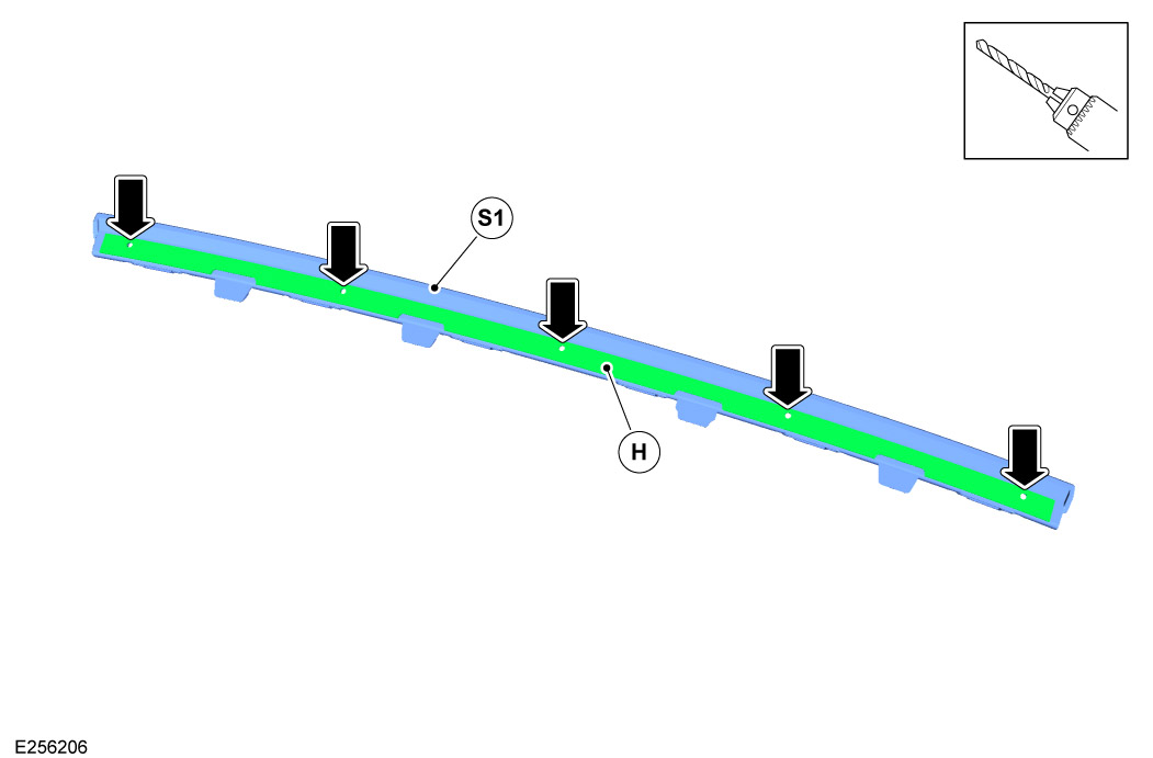
Using the strengthening bar as a guide (H), drill the x5 locations on the lower bumper grille part (S1), retained from step 67. Countersink the holes produced in part (S1) for the screws (K1) on the opposite side.

  • 4mm drill bit
70

Trim and install safe edge (P) to the lower bumper grille part (S1).

71
NOTE
  • Appearance of the front bumper cutout will vary depending on if the front bumper has been configured for the winch or the bull bar cradle.

Assemble and install the front bumper to the vehicle.

  • Log into TOPIX and enter your 17 character 'Vehicle Identification Number' and navigate to 'Workshop Manual' section '501-19 Bumpers'.
72
CAUTION
  • This step must be done when the bumper is back on the vehicle - if done off the vehicle then if the bumper is bowed, the strengthening plate will not be in the correct position.
NOTE
  • Image looking from underneath part.

Install the strengthening bar (H) to the front bumper carrier.

  1. Locate the strengthening bar (H) to the front bumper carrier.
  2. Install the lower bumper grille (S1) over the strengthening bar (H) using the x5 fixings (K1).
73

Connect the 12V battery.

  • Log into TOPIX and enter your 17 character 'Vehicle Identification Number' and navigate to 'Workshop Manual' section '414-00 12V System Disconnect and Connect'.
74

Refer to bull bar instructions for installation of the bull bar.

75
CAUTION
  • Make sure the license plate plinth is installed correctly and is not distorted.
NOTE
  • Complete step only if required.

Install the license plate plinth and plate.

© Land Rover 2016