LAND ROVER ACCESSORY FITTING INSTRUCTIONS

VEHICLE :
PART NO :
KEYWORD :

LAND ROVER

RANGE ROVER EVOQUE

TOW BAR - DEPLOYABLE

VPLZT0309 / LR143646 / VPLKT0318 / LR114849 - LR117424

FITTING INSTRUCTION

WARNING
  • Accessories which are not correctly installed can be dangerous. Read the instructions carefully prior to installation. Comply with instructions at all times. If in doubt, contact your nearest approved retailer.
CAUTION
  • Under no circumstances is the motor to be removed from the towbar armature when being replaced. The complete armature assembly needs to be returned otherwise any claim will be rejected.
NOTE
  • The towbar wiring harness (B) (LR143646), tow eye cover (H) (LR114849) or (LR117424) and towbar control module (A) (VPLKT0318) are not included in the deployable towbar kit. These parts must be ordered separately.
  • The variant of the tow eye cover that must be ordered is dependent on the type of rear bumper installed on the vehicle. if the vehicle has a rear standard bumper then order tow eye cover (LR114849). If the vehicle has a rear dynamic bumper then order tow eye cover (LR117424).
  • If the vehicle has a rear dynamic bumper then the tow eye cover (LR117424) must be painted to match the vehicle body color. The tow eye cover is supplied with only primer applied.
Specifications
Type Brink 617305-00
D-value 10.96 kN
Vertical coupling load 150 kg
Coupling class A50-X
Manufacturer Brink Towing Systems B.V.
Model application Range Rover Evoque
EC-type approval number towbar E11 55R-0110898
Maximum trailer weight 2000 kg
REMOVAL INSTRUCTIONS
1

Disconnect the 12 V battery. For additional information, please refer to the official Workshop Manual. 12V System Disconnect  (414-00 Battery and Charging System - General Information)

2

Fold down 2nd row seats. Refer to Owner's Handbook if unsure how to do this.

3

Remove.

  1. Remove parcel shelf.
  2. Remove loadspace cover.
4

Remove.

  1. Release tailgate weather strip.
  2. Remove loadspace treadplate from its (x6) clips.
5
NOTE
  • If your vehicle does not have a spare wheel then you will also need to remove the right loadspace side trim.

Remove left loadspace side trim. For additional information, please refer to the official Workshop Manual. Left Loadspace Side Trim Panel (501-05 Interior Trim and Ornamentation) Remove right loadspace side trim if required. For additional information, please refer to the official Workshop Manual. Right Loadspace Side Trim Panel (501-05 Interior Trim and Ornamentation)

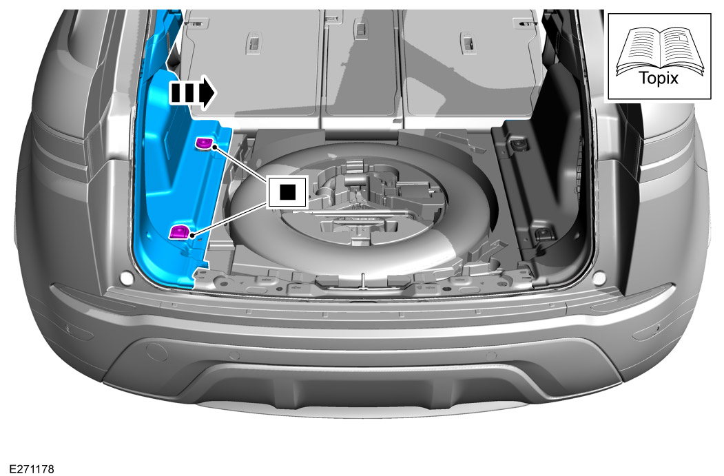
  • D-loops anchor points shown. Alternatively luggage rail could be installed instead, that will need removing as well.
6

Remove the illustrated cover from the left loadspace trim panel and remove the power socket from the cover and retain.

7
NOTE
  • Appearance of the loadspace stowage compartment will vary depending on the vehicle specification.

Remove spare wheel (if present). Or tool foam trays (*).

  1. Remove tool foam tray.
  2. Unscrew spare wheel lock down bolt and remove spare wheel.
8
NOTE
  • Vehicles with spare wheel only.

Remove left load compartment foam floor trim.

9

Remove and discard the grommet and bezel located in the spare wheel well.

10

Raise vehicle on post ramp.

11

Remove rear lights and bumper.

  1. Remove outer tail lamps. For additional information, please refer to the official Workshop Manual. Outer Tail Lamp (417-01 Exterior Lighting)
  2. Remove rear bumper. For additional information, please refer to the official Workshop Manual. Rear Bumper (501-19 Bumpers)
12

Remove the rear valance and retain the (x6) fixings.

13

Remove and retain the (x2) illustrated brackets and (x4) fixings.

14
WARNING
  • This step requires the assistance of another person.

Remove (x8) fixings and remove rear bumper armature.

15
WARNING
  • Observe due care when working near a hot exhaust system.
CAUTION
  • Make sure the exhaust system is supported at all times.
NOTE
  • This step is only for 2.0L diesel exhaust system with diesel exhaust fluid tank.

Release and drop rear section of exhaust and the diesel exhaust fluid tank significantly enough to gain to hidden fixings.

  1. Rear exhaust section. For additional information, please refer to the official Workshop Manual. Rear Silencer (309-00 Exhaust System - INGENIUM I4 2.0L Diesel AJ21)
  2. Diesel exhaust fluid tank. For additional information, please refer to the official Workshop Manual. Diesel Exhaust Fluid Tank (303-08 Engine Emission Control - INGENIUM I4 2.0L Diesel AJ21)
16
WARNING
  • Observe due care when working near a hot exhaust system.
CAUTION
  • Make sure the exhaust system is supported at all times.
NOTE
  • This step is only for 2.0L petrol exhaust system.

Release and drop rear section of exhaust for 2.0L Petrol significantly enough to gain access to hidden fixings. For additional information, please refer to the official Workshop Manual. Rear Silencer (309-00 Exhaust System - INGENIUM I4 2.0L Petrol)

17
WARNING
  • Observe due care when working near a hot exhaust system.
CAUTION
  • Make sure the exhaust system is supported at all times.
NOTE
  • This step is only for the Plug-in Hybrid Electric Vehicle (PHEV) 1.5L petrol exhaust system.

Release and drop rear section of exhaust significantly enough to gain access to hidden fixings. For additional information, please refer to the official Workshop Manual. Rear Silencer (309-00 Exhaust System - INGENIUM I3 1.5L Petrol, Vehicles With: PHEV)

18
NOTE
  • This step is only for 2.0L diesel exhaust system.

Remove (x5) fixings to remove exhaust heatshield.

19

Removal steps.

  1. Remove (x2) fixings and slide out the tow eye on the left side of vehicle.
  2. Remove (x2) fixings on the right side of vehicle and slide out the diesel exhaust fluid tank reinforcement bracket. This step is only for vehicles with diesel exhaust fluid tank present.
Fitting Instruction
1
WARNING
  • This step requires the assistance of another person.
NOTE
  • Only hand tighten fixings at this stage.

Install the towbar (D) to the vehicle and hand tighten with (x4) fixings (D2).

2
NOTE
  • Only hand tighten fixings at this stage.

Hand tighten (x8) fixings (D1).

3

Tighten the (x4) fixings.

  • Torque 170 Nm
4

Tighten fixings in the sequence shown.

  • Torque 100 Nm +240° +/-5°
5

Reinstall 2 brackets with (x4) fixings that were removed in removal step 13.

6
NOTE
  • This step is only for 2.0L diesel exhaust system with diesel exhaust fluid tank.

Reinstall exhaust heatshield with (x5) fixings.

7
NOTE
  • Reinstall exhaust sections

Reinstall exhaust sections (see removal steps 15 to 17).

8

Lower vehicle on post ramp.

9

Install the Towbar Control Module (TBM) (A) to the inner left side rear floor with (x2) fixings (A1).

  • Torque 5 Nm
10
NOTE
  • Make note of towing harness (B) connectors.

Familiarize yourself with towing harness (B).

11

Follow sequence to complete step.

  1. Feed the towbar wiring harness (B) through the hole in the spare wheel well. So (BI) (BK) and (BJ) are on the outside of vehicle.
  2. Install the grommet (BA) to spare wheel well.
  3. Install connector (BB) to existing body harness (Yellow).
  4. Install other connectors and clips as illustrated.
12

Follow sequence to complete step.

  1. Attach towbar harness ground point (BC) using the ground bolt (B1).
  2. Torque 10 Nm for ground bolt.
  3. Clip rest of towbar harness to body harness as illustrated.
13

Install left side floor foam trim.

14

Install speaker.

  1. Install speaker (C) into floor foam trim.
  2. Connect speaker (C) to towbar harness connector (BE).
15

Follow sequence to complete step.

  1. Clip towbar harness (shown with arrows) to bumper support bracket.
  2. Connect connectors to towbar as illustrated.
16

Prepare and install the tow eye cover (H) (LR117424 or LR114849).

  1. Paint the tow eye cover (H) to match the vehicle body color if you are installing (LR117424). The tow eye cover is supplied with only primer applied.
  2. Install the tow eye cover (H) (LR117424 or LR114849) using the (x6) fixings removed in removal step 12.
17

Reinstall rear lights and bumper.

  1. Reinstall rear bumper For additional information, please refer to the official Workshop Manual. Rear Bumper (501-19 Bumpers)
  2. Reinstall outer tail lamps For additional information, please refer to the official Workshop Manual. Outer Tail Lamp (417-01 Exterior Lighting)
18
NOTE
  • For vehicles with spare wheel only.

Reinstall the remainder of left load compartment foam floor trim removed in removal step 8.

19

Reinstall spare wheel or foam tray that were removed in removal step 7.

20

Install towbar switch (F) into switch bezel (E). Then install the power socket removed from removal step 6.

21

Install the deployable towbar switch bezel (E) onto the left loadspace trim panel.

22
NOTE
  • When reinstalling the left loadspace side trim connect towbar harness connector (BD) to towbar switch (F).

Reinstall left loadspace side trim. For additional information, please refer to the official Workshop Manual. Left Loadspace Side Trim Panel (501-05 Interior Trim and Ornamentation) And right loadspace side trim if required. For additional information, please refer to the official Workshop Manual. Right Loadspace Side Trim Panel (501-05 Interior Trim and Ornamentation)

  • D-loops anchor points shown. Alternatively luggage rail could be reinstalled instead.
23

Connect the 12 V battery. For additional information, please refer to the official Workshop Manual. 12V System Disconnect  (414-00 Battery and Charging System - General Information)

24
NOTE
  • Make sure step 1 is successfully completed before proceeding to step 2.

Use the JLR approved diagnostic equipment to navigate to 'Diagnostics' section and follow the steps below.

  1. Within Vehicle Applications – Click ‘RUN’ for ‘Add/Remove Electronically Deployable Towbar’, then choose ADD.
  2. Within Module Programing – Click ‘RUN’ for ‘TBM - Software - Replace Module’.
  3. To enable the changes on the vehicle
    Ignition off
    Close all doors
    Lock the vehicle
    Wait 5 minutes
    To confirm changes
    Unlock the vehicle
    Reset Infotainment Screen (Refer to 'Touchscreen' settings in Owners handbook for detailed procedure.)
    Confirm ‘Tow bar' tile is present on the Touchscreen.
25

Reinstall loadspace treadplate and tailgate weather strip (reversal of removal step 4).

26

Store the tow eye (G) in the foam block or the tire repair kit stowage compartment when not being used.

27

Reinstall loadspace cover and parcel shelf (reversal of removal step 3).

28

Fold up 2nd row seats.

29

Inspect the operation of the trailer lamps and the vehicle lamps. Both trailer and vehicle lights must be synchronised.

© Land Rover 2016