LAND ROVER ACCESSORY FITTING INSTRUCTIONS

VEHICLE :
PART NO :
KEYWORD :

LAND ROVER

DISCOVERY

MULTI-HEIGHT TOWBAR

VPLRT0175 / VPLYT0295 / FS106256 / FN106042 / VPLRV0131 / LR146570 / VPLRT0345 / LR142607 / LR142610

FITTING INSTRUCTION

WARNING
  • Accessories which are not correctly installed can be dangerous. Read the instructions carefully prior to ordering and installation to make sure this accessory is applicable to your variant of vehicle. Comply with instructions at all times. If in doubt, contact your nearest approved retailer.

Multi-height Towbar - VPLRT0175 (Bill of Materials)

NOTE
  • For motor vehicle data please see page at the end of these instructions.
Bill Of Materials
(A) Towbar
(A1) Bolt - M14x148
(A2) Bolt - M14x55
(B) Shield Bracket
(B1) Bolt - M6x25
(B2) Nut - M6
(C) Shield
(C1) Push Clips
(D) Towing Electrical Socket
(D1) Screw - M5x35
(D2) Nut - M5
(E) Plate
(E1) Bolt - M16x30
(E2) Nut - M16x30
(F) Spacer
(G) Tow Ball
(G1) Bolt - M16x60

Additional Parts Required (Bill of Materials)

NOTE
  • If you vehicle has 'Deployable Side Steps' already installed then items (I, H1 and H2) will not be required.
Bill Of Materials Service Part Number
(H) Trailer Module (TRM) VPLYT0295
(H1) Bolt FS106256
(H2) Nut FN106042
(I) TRM Bracket VPLRV0131
(J) Towing Harness LR146570
(K) Link Lead VPLRT0345
(L) Base Rear Bumper Valance LR142607
(L) Dynamic Rear Bumper Valance LR142610

Painting Required

NOTE
  • The Dynamic Rear Bumper Valance (L) - LR142610, needs to be painted body color before installation. Please see table above to identify your correct bumper parts.

Tooling

Tooling
Screwdrivers - Cross-head and Torx
Ratchet and Socket set
Torque Wrench - 5Nm to 330Nm
4 Post Vehicle Lift
Jaguar Land Rover Approved Diagnostic Equipment
Measuring Ruler
Marker Pen
Drill and metal drill bits 4mm and 6.5mm
Fitting Instruction
1

Open tailgate and remove the deployable loadspace floor hinge.

  • For additional information, please refer to the official Workshop Manual. Deployable Loadspace Floor Hinge (501-05)
2

Remove loadspace rubber mat.

3

Raise the loadspace stowage compartment.

  1. Release both latches.
  2. Raise the loadspace stowage compartment.
4

Remove x7 fixings and remove loadspace stowage tray.

5

Pull away rear scuff plate from its x4 clips to remove.

6

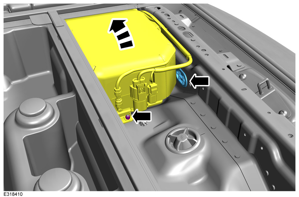
Remove back panel seal. And if applicable to your vehicle, remove the bolt on the air suspension supply unit. This will allow you to slightly move the unit to grain easier access to installing the towing harness.

7

Remove the left loadspace trim panel.

  • For additional information, please refer to the official Workshop Manual. Left Loadspace Trim Panel (501-05)
8

Select the following steps that are applicable to your variant of vehicle.

  1. If you vehicle HAS 'Deployable Side Steps' already installed then follow steps 9 to 15. Then jump to step 19.
  2. If you vehicle does NOT have 'Deployable Side Steps' already installed then follow steps 16 to 18.
9
NOTE
  • Area shown is located on the rear floor of the vehicle where you have removed the left loadspace trim panel.

Disconnect Running Board Control Module (RBM) .

  1. Disconnect cable (X) from RBM.
  2. Disconnect cable (Y) from RBM.
10

Remove x2 fixings and remove RBM with bracket.

11

Remove fixings that hold the RBM to bracket.

12

Install the TRM(H) to underside of bracket and secure with the same fixings removed in previous step.

  • Torque: 5Nm
13

Install x2 fixings removed in step 10 to install module bracket to vehicle.

  • Torque: 5Nm
14

Connect towing harness (J) to the TRM(H).

  • Clip towing harness (J) to module bracket where arrowed. And connect x2 connectors to the TRM(H).
15

Connect RBM.

  1. Reconnect cable (X) back to the RBM and towing harness (J).
  2. Reconnect cable (Y) back to the RBM.
16

Install the TRM(H) to underside of bracket (I) with x2 fixings (H1) and (H2).

  • Torque: 5Nm
17
NOTE
  • Area shown is located on the rear floor of the vehicle where you have removed the left loadspace trim panel.

Install the bracket (I) to vehicle using x2 fixings (H2).

  • Torque: 5Nm
18

Connect towing harness (J) to TRM(H) and the main body harness.

  1. Clip towing harness (J) to module bracket where arrowed. And connect x2 connectors to the TRM and remaining connector to the main body harness.
19

Install towing harness (J) to inner back panel.

  1. Clip towing harness (J) to inner back panel where shown with a black arrow.
  2. Feed remaining harness through the hole in the inner back panel and secure grommet where shown with a white arrow.
20

Raise and support vehicle on a 4 post ramp.

  • For additional information, please refer to the official Workshop Manual. Jacking and Lifting (100-02)
21

Remove the rear bumper.

  • For additional information, please refer to the official Workshop Manual. Rear Bumper (501-19)
22
WARNING
  • Observe due care when working near a hot exhaust system. Make sure the exhaust system is supported at all times.
  • Heavy component, risk of injury. Two persons are required for this step.

Lower rear exhaust and remove and discard the rear bumper armature.

  • For additional information, please refer to the official Workshop Manual. Rear Armature (501-19)
23
NOTE
  • Use a cooling spray/oil to reduce heat when drilling.

Drill x4 holes on towbar (A).

  1. Drill x4 pilot holes at 4mm diameter.
  2. Increase x4 holes to 6.5mm diameter.
  3. Using a deburring tool, tidy up drilled holes.
  4. Then apply some corrosion paint to the drilled holes for protection.
24

Install the shield bracket (B) to the rear of the towbar (A) with fixings (B1) and (B2).

  • Torque: 12Nm
25

Install the towing electrical socket (D) to the bracket on the towbar (A) with fixings (D1) and (D2). Then push the harness clip into the hole underside of towbar (A) where arrowed.

26

Install the shield (C) to the towbar (A) with push clips (C1).

27
WARNING
  • Heavy component, risk of injury. Two persons are required for this step. When in position, one person will need to hold it in place while the other installs the fixings.
NOTE
  • Do NOT fully tighten fixings at this stage.

Offer up towbar (A) into position and secure with x8 fixings (A2).

28

Install x2 fixings (A2).

  • Torque: 100Nm. Then tighten fixings an extra 120° turn.
29

Install x4 fixings (A1).

  • Torque: 100Nm. Then tighten fixings an extra 240° turn.
30

Torque x8 fixings (A2).

  • Torque: 100Nm. Then tighten fixings an extra 120° turn.
31

Clip towing harness (J) connector to towbar (A) using the pre-drilled holes.

32

Install link lead (K).

  1. Connect link lead (K) to the towing electrical socket (D) and towing harness (J).
  2. Clip the link lead (K) to the vehicle where arrowed.
33
NOTE
  • Fixing plate (E) is only required if you are installing to the lowest position.

Install the towball. Please see following steps on how to install for upper, middle or lower positions.

34
NOTE
  • Do not use the fixing plate (E) for this position.

For using the towball in the top position follow these instructions.

  • Torque: 330Nm
35
NOTE
  • Do not use the fixing plate (E) for this position.

For using the towball in the middle position follow these instructions.

  • Torque: 330Nm
36

For using the towball in the lowest position follow these instructions.

  • Torque: 330Nm
37

Install the rear exhaust system and rear bumper support brackets.

  • For additional information, please refer to the official Workshop Manual. Rear Armature (501-19)
38

Install the new rear bumper valance (L) to the rear bumper. Remove the old valance from the bumper if it is still in place.

  • For additional information, please refer to the official Workshop Manual. Rear Bumper (501-19)
39

Install the rear bumper.

  • For additional information, please refer to the official Workshop Manual. Rear Bumper (501-19)
40

Lower the vehicle on the 4 post ramp.

41
NOTE
  • When this step is complete you can then reinstall the trim removed.

Using the Jaguar Land Rover approved diagnostic equipment, configure the towbar electrics.

42

If applicable to your vehicle, install the fixing to secure the air suspension supply unit.

  • Torque: 10.5Nm
43

Install the left loadspace trim panel.

  • For additional information, please refer to the official Workshop Manual. Left Loadspace Trim Panel (501-05)
44

Clip rear scuff plate back into position with x4 clips.

45

Install loadspace stowage tray with x7 fixings.

46

Lower the loadspace stowage compartment.

47

Install loadspace rubber mat.

48

Install the deployable loadspace floor hinge. Then raise it to its upward position before closing the tailgate.

  • For additional information, please refer to the official Workshop Manual. Deployable Loadspace Floor Hinge (501-05)
49

Motor Vehicle Data sheet

Motor vehicle data, Multi-height Towbar Specifications
Type Brink 5774
D-value 16.32 kN
Vertical coupling load 350 kg
Coupling class A50-X
Manufacturer Brink Towing Systems B.V.
Model application Land Rover Discovery
EC-Type Approval No E11 55R-0110727
Max. Trailer Weight 3500 kg
© Land Rover 2016