SELECT YOUR LANGUAGE
Open all doors and raise and support the vehicle.
If installed to your vehicle then remove both 'Front Mudflaps'.
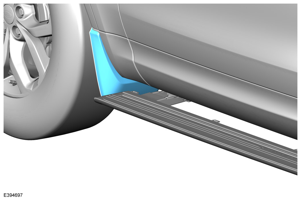
Remove both front fender moulding (X) and rocker panel moulding.
Remove the transmission undershield.
Remove both underbody side shields.
Modify both removed underbody side shields. Stage 1 of 3.
Modify both removed underbody side shields. Stage 2 of 3.
Modify both removed underbody side shields. Stage 3 of 3.
Cutting foam pad (J).
Install the foam pad (J).
Install both front side step mounting brackets (A1) and (B1).
Install front spacers (F).
Install both rear side step motor mounting brackets (A2) and (B2).
Install both side steps (N) for correct alignment.
Tighten 3 fixings (C) on both front brackets. Torque: 48Nm
Tighten fixing (C) on both rear motor brackets. Torque: 48Nm
Tighten 2 fixings (C) on both front brackets. Torque: 48Nm
Tighten 2 fixings (C) on both rear motor brackets. Torque: 48Nm
Remove both side steps.
Install both modified underbody side shield sections.
Install the transmission undershield.
Install part (G) to the removed front fender moulding (X) from 'Step 3'.
Install both front and rocker panel moulding and front fender moulding (X).
Install both side steps (N).
If applicable to your vehicle, install both 'Front Mudflaps'.
Test the function of the 'Deployable Side Steps'.