LAND ROVER ACCESSORY FITTING INSTRUCTIONS

VEHICLE :
PART NO :
KEYWORD :

LAND ROVER

DISCOVERY

DEPLOYABLE SIDE STEP WIRING HARNESS

VPLRP0328 / VPLRP0361

FITTING INSTRUCTION

WARNING
  • Accessories which are not properly fitted can be dangerous. Read the instructions carefully prior to fitting. When fitting, comply with instructions at all times. If in doubt, contact your nearest approved retailer.
NOTE
  • This procedure contains some variation in the illustrations depending on the vehicle specification, but the essential information is always correct.
  • The wiring harness routing is the same for both 5 and 7 seat vehicle variants.
  • The factory fitted deployable towing module does not have deployable side step capability and needs to be replaced with Tow Bar Control Module (TBM) (B) (VPLRP0361) when the vehicle has both electric deployable towing and deployable side steps fitted.
Fitting Instruction
1
NOTE
  • For 5 seat vehicles see steps 1 to 6 then continue to step 13. For 7 seat vehicles see steps 7 to 12 then continue to step 13.

Remove the loadspace floor panel.

2

Remove the loadspace stowage former.

3

Remove the loadspace floor beam.

4

Remove the fixed D-loop anchor points.

5

Remove the loadspace infil trims.

6

Remove the loadspace underfloor trim.

7
NOTE
  • For 7 seat vehicles see steps 7 to 12 then continue to step 13.

Remove the loadspace floor panel.

8

Remove the fixed D-loop anchor points.

9

Remove the loadspace infil trims.

10

Remove the seat bezel trims.

11

Remove the loadspace floor liner trim.

12

Remove the loadspace infil rail carriers.

13

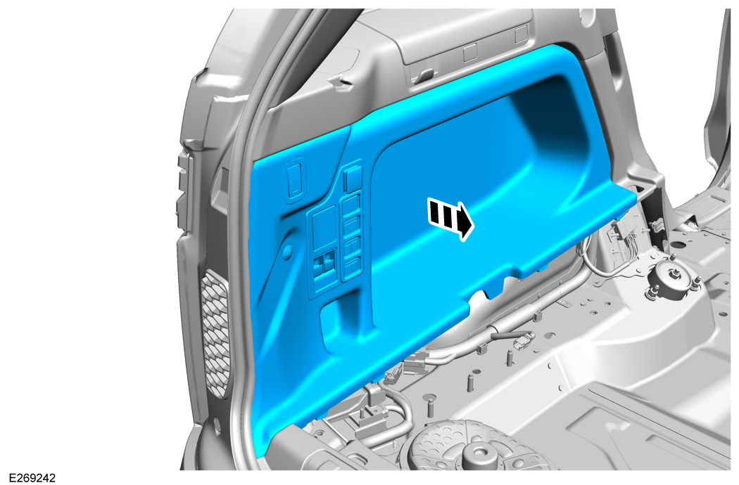
Remove both left and right loadspace trim panels.For additional information, please refer to the official Workshop Manual. Left Loadspace Trim Panel (501-05) For additional information, please refer to the official Workshop Manual. Right Loadspace Trim Panel (501-05)

14
NOTE
  • Complete this step if you have deployable loadspace floor installed.

Aside the deployable loadspace floor strut for access.

15

Disconnect the vehicle startup battery. For additional information, please refer to the official Workshop Manual. Startup Battery (414-01)

16
NOTE
  • Complete this step for 7 seat vehicles only.

Remove the cup holder trim.

17
NOTE
  • Complete this step for 7 seat vehicles only.

Remove the third row seat trim.

18

Remove the lower C-pillar trim on both sides of the vehicle. For additional information, please refer to the official Workshop Manual. C-Pillar Lower Trim Panel - [+] Vehicles with 2nd / 3rd Row Seats (501-05)

19

Lift up the rear of the main floor trim.

20
NOTE
  • Complete this step for vehicles with factory fitted 3 connector towbar module installed.

Unplug and discard the factory fitted towbar module as this does not have DSS capability.

21

Install the TBM (B).

  • Torque: 5 Nm.
  • Connect the electrical body harness.
22

Plug in the deployable side step harness (A) to the TBM.

23
CAUTION
  • Do not fully tighten cable ties.

Route and attach the wiring harness (A) from the TBM as illustrated.

24
CAUTION
  • Do not fully tighten cable ties.
NOTE
  • Part (A2) refers to the section of harness (A) which splits out and runs across the vehicle.
  • Secure any excess of harness (A2) with cable ties where arrowed.

Route and attach the wiring harness (A) as illustrated.

25
NOTE
  • 7 seat variant shown.
  • Left side shown, right side similar.
  • If applicable clip the wiring harness to the third row seat bracket.

For 7 seat variants secure the wiring harness to the bracket in the clip position illustrated.

26
NOTE
  • Remove blanking grommets, feed the harness through the hole and securely fit the new grommet.

Place the harness (A2) across the vehicle floor and securely tape the wiring harness on the body and air ducting as shown.

27
CAUTION
  • Do not fully tighten cable ties.
NOTE
  • Right side shown.
  • Tape the harness on the air ducting as shown.
  • For 7 seat variants secure the wiring harness to the seat bracket.
  • Remove blanking grommets, feed the harness through the hole and securely fit the new grommet.

Secure and tape the harness section (A2) to the body as shown.

28

When a satisfactory position for the wiring harness is achieved fully tighten all cable ties.

29

Release the front of the rear wheel arch liner for access. For more information refer to Deployable side steps fitting instructions.

30
NOTE
  • Right side shown. Left side similar.
  • Secure the grommets.
  • Plug the wiring harness into the rear side step brackets.

Feed the wiring harness through the rear wheel arch area and secure as illustrated.

31

Replace fuse in location 39 in the rear junction box with fuse 'D' supplied.

32

Connect the vehicle startup battery. For additional information, please refer to the official Workshop Manual. Startup Battery (414-01)

33

Using the Jaguar Land Rover approved diagnostic equipment, configure the deployable side step electrics.

34
NOTE
  • Complete this step if you have deployable loadspace floor installed.

Install the deployable loadspace floor strut back into position.

35

Install the lower C-pillar trim on both sides of the vehicle. For additional information, please refer to the official Workshop Manual. C-Pillar Lower Trim Panel - [+] Vehicles with 2nd / 3rd Row Seats (501-05)

36
NOTE
  • Complete this step for 7 seat vehicles only.

Install the third row seat trim removed in step 17.

37
NOTE
  • Complete this step for 7 seat vehicles only.

Install the cup holder trim removed in step 16.

38

Install the left and right loadspace trim panels.For additional information, please refer to the official Workshop Manual. Left Loadspace Trim Panel (501-05) For additional information, please refer to the official Workshop Manual. Right Loadspace Trim Panel (501-05)

39
NOTE
  • Complete this step for 5 seat vehicles only.

Install trims removed in steps 6-1.

40
NOTE
  • Complete this step for 7 seat vehicles only.

Install trims removed in steps 12-7.

© Land Rover 2016