LAND ROVER ACCESSORY FITTING INSTRUCTIONS

VEHICLE :
PART NO :
KEYWORD :

LAND ROVER

RANGE ROVER SPORT

TOWING SYSTEMS

VPLXT0344 / VPLXT0343 / VPLXT0333 / VPLKT0326 / VPLKT0325 / VPLKT0318 / VPLYT0295 / VPLXT0343 / VPLXT0344 / LR173054 / LR166804 / LR166805 / FN106042 / VPLKT0323 / VPLKT0324 / LR185391 / LR185392 / LR81861

FITTING INSTRUCTION

WARNING
  • Accessories which are not correctly installed can be dangerous. Read the instructions carefully prior to ordering and installation to make sure this accessory is applicable to your variant of vehicle. Comply with instructions at all times. If in doubt, contact your nearest approved retailer.
  • Any parts discarded must be recycled in a environmentally responsible manner making sure all local laws are adhered to.

Deployable Towbar (Bill of Materials)

NOTE
  • Inspect contents of kits to make sure that all the parts shown in the BOM image below are present.
  • The items (B, C, E and E1) do not come in the towbar kit - VPLXT0333 and must be ordered separately.
  • x2 M6 Fixings (E1) - FN106042 kits will need to be ordered as only one comes in each kit.
  • For motor vehicle data see sheet at the end of these instructions.
  • For SV vehicles a specific 'Deployable Tow Eye Cover' (C) - LR185392 will need to be ordered. This part is delivered primed and must be painted (see step 1).
Bill Of Materials Replacement Service Part Number
(A) Towbar VPLXT0333
(A1) Fixing - M12x55 - x4 W780893
(A2) Fixing - M14x55 - x6 W713336
(B) Deployable Towbar Harness LR173054
(B) Deployable Towbar Harness (Australian market only) LR166805
(C) Deployable Tow Eye Cover - Narvick Black (NON-SV Vehicles 'ONLY') VPLXT0343
(C) Deployable Tow Eye Cover SV - Primed (SV Vehicles 'ONLY') LR185392
(D) Recovery Eye Available in complete kit only
(E) Towbar Control Module (TBM) VPLKT0318
(E1) Fixing - M6 - x2 FN106042
(F) Label (Australian market only) LR81861

NAS Receiver Towbar (Bill of Materials)

NOTE
  • Inspect contents of kits to make sure that all the parts shown in the BOM image below are present.
  • The items (B, C, E and E1) do not come in the towbar kit - VPLK0326 and must be ordered separately.
  • x2 M6 Fixings (E1) - FN106042 will need to be ordered as only one comes in each kit.
  • For motor vehicle data see sheet at the end of these instructions.
  • For SV vehicles a specific 'Tow Eye Cover' (C) - LR185391 will need to be ordered. This part is delivered primed and must be painted (see step 1).
Bill Of Materials Replacement Service Part Number
(A) Towbar VPLKT0326
(A1) Fixing - M12x55 - x4 W780893
(A2) Fixing - M14x55 - x6 W713336
(B) Towbar Harness LR166804
(C) Tow Eye Cover - Narvick Black (NON-SV Vehicles 'ONLY') VPLXT0344
(C) Tow Eye Cover SV - Primed (SV Vehicles 'ONLY') LR185391
(D) Recovery Eye Available in complete kit only
(E) Trailer Module (TRM) VPLYT0295
(E1) Fixing - M6 - x2 FN106042
(F) Australian Towbar Hitch VPLKT0324

Australian Receiver Towbar (Bill of Materials)

NOTE
  • Inspect contents of kits to make sure that all the parts shown in the BOM image below are present.
  • The items (B, C, E and E1) do not come in the towbar kit - VPLK0325 and must be ordered separately.
  • x2 M6 Fixings (E1) - FN106042 will need to be ordered as only one comes in each kit.
  • For motor vehicle data see sheet at the end of these instructions.
  • For SV vehicles a specific 'Tow Eye Cover' (C) - LR185391 will need to be ordered. This part is delivered primed and must be painted (see step 1).
Bill Of Materials Replacement Service Part Number
(A) Towbar - x1 VPLKT0325
(A1) Fixing - M12x55 - x4 W780893
(A2) Fixing - M14x55 - x6 W713336
(B) Towbar Harness - x1 LR166804
(C) Tow Eye Cover - Narvick Black (NON-SV Vehicles 'ONLY') VPLXT0344
(C) Tow Eye Cover SV - Primed (SV Vehicles 'ONLY') LR185391
(D) Recovery Eye - x1 Available in complete kit only
(E) TRM - x1 VPLYT0295
(E1) Fixing - M6 - x2 FN106042
(F) Australian Towbar Hitch VPLKT0323

Tooling

Tooling
Trim Removal Tool
T30 bit
Ratchet
Socket - 10, 15, 18mm
Torque Wrench
4 Pillar Vehicle Lift
Approved Diagnostic Equipment
Fitting Instruction
NOTE
  • This procedure contains some variation in the illustrations depending on vehicle and towbar specification, but the essential information is always correct.
  • Place vehicle on 4 Pillar ramp before you start this procedure.
1
NOTE
  • This step is 'ONLY' applicable to SV vehicles.

The SV 'Rear Tow Eye Cover' (C) must be painted with the body color paint (individual color for each vehicle) before installing on the bumper.

2

Open tailgate and remove 'Loadspace Blind' and 'Loadspace Floor'.

3

Remove spare wheel or foam tool tray depending on your vehicle specification.

4

Remove x1 fixing from the left side luggage compartment treadplate.

5

Remove x1 clip to release the luggage space liner.

6

Pull back the luggage space liner on left side rear corner to expose inner back panel.

7

Remove grommet from inner back panel.

8
NOTE
  • TBM shown. TRM similar.

Install the TBM or TRM(E) to the inner back panel with x2 fixings (E1).

  • Torque 6Nm
9
NOTE
  • This step is 'ONLY' applicable for 'Deployable Towbar'. For Australian and NAS receiver towbars jump to step 11.

Familiarize yourself with the 'Towbar Harness' (B).

10
NOTE
  • This step is 'ONLY' applicable for 'Deployable Towbar'.
  • For deployable towbar in Austrailian Market only, use harness 'LR166805'.
  • An audible click will be heard when the connectors are correctly connected.

Install 'Towbar Harness' (B).

  1. Feed towbar harness through the rear inner panel so connectors (BA, BB and BH) are on the outside the vehicle. Then secure with grommet (BC).
  2. Secure towbar harness to the vehicle with x3 clips (shown in illustration with black arrows).
  3. Connect ground point (BD) to rear inner back panel stud. Use fixing that is already attached to the stud. Torque: 10Nm
  4. Connect towbar harness to TBM with connectors (BE, BI and BF).
  5. Connect connector (BG) to the main body harness. Then jump to step 13.
11
NOTE
  • This step is 'ONLY' applicable for Australian and NAS receiver towbars.

Familiarize yourself with the 'Towbar Harness' (B).

12
NOTE
  • This step is 'ONLY' applicable for Australian and NAS receiver towbars.
  • An audible click will be heard when the connectors are correctly connected.

Install 'Towbar Harness' (B).

  1. Feed towbar harness through the rear inner panel so connectors (BA and BB) are on the outside the vehicle. Then secure with grommet (BC).
  2. Secure towbar harness to the vehicle with x3 clips (shown in illustration with black arrows).
  3. Connect ground point (BD) to rear inner back panel stud. Use fixing that is already attached to the stud. Torque: 10Nm
  4. Connect towbar harness to TRM with connectors (BE and BF).
  5. Connect connector (BG) to the main body harness.
13
NOTE
  • Make sure step 1 is successfully completed before proceeding to step 2.

Use the approved diagnostic equipment to navigate to 'Diagnostics' section and follow the steps below.

  1. Within Vehicle Applications – Click ‘RUN’ for ‘Add/Remove Electronically Deployable Towbar’, then choose ADD.
  2. Within Module Programing – Click ‘RUN’ for ‘TBM - Software - Replace Module’.
  3. To enable the changes on the vehicle
    Ignition off
    Close all doors
    Lock the vehicle
    Wait 5 minutes
    To confirm changes
    Unlock the vehicle
    Reset Infotainment Screen (Refer to 'Touchscreen' settings in Owners handbook for detailed procedure.)
    Confirm ‘Tow bar' tile is present on the Touchscreen.
14

Fold back the luggage space liner.

15

Install x1 clip to the luggage space liner.

16

Install x1 fixing to secure the left side luggage compartment treadplate.

17

Install spare wheel or foam tool tray depending on your vehicle specification.

18

Install 'Loadspace Blind' and 'Loadspace Floor'.

19

Raise vehicle on ramp.

20
NOTE
  • This step is 'ONLY' applicable for vehicles with rear 'Mud Flaps' installed.
  • The rear wheel is removed on the graphic for clarity and does not need to be removed.

If the rear 'Mud Flaps' are installed then you will need to remove x3 fixings on each rear mud flap on both sides of the vehicle to remove the rear mud flaps.

21
NOTE
  • This step requires the aid of another person.
  • Make sure to retain all fixings.
  • Tools to remove the rear bumper are not covered in the 'Tooling'.

Remove rear bumper and the tow eye cover from the bumper. See TOPIx section 501-19 for workshop manual procedure:

  • For additional information, please refer to the official Workshop Manual. Rear Bumper Cover (501-19 Bumpers)
22
WARNING
  • Observe due care when working near a hot exhaust system. Make sure the exhaust system is supported at all times.
NOTE
  • Petrol exhaust shown, but the essential information is always correct for other exhaust variants.

Remove rear exhaust silencer'. See TOPIx section 309 for workshop manual procedure:

  • 3.0L Petrol - For additional information, please refer to the official Workshop Manual. Exhaust System (309-00 Exhaust System - INGENIUM I6 3.0L Petrol)
  • 3.0L Petrol Plug-in Hybrid Electric Vehicle (PHEV) - For additional information, please refer to the official Workshop Manual. Rear Silencer (309-00 Exhaust System - INGENIUM I6 3.0L Petrol - PHEV)
  • 3.0L Diesel - For additional information, please refer to the official Workshop Manual. Rear Silencer (309-00 Exhaust System - INGENIUM I6 3.0L Diesel)
  • 4.4L Petrol - For additional information, please refer to the official Workshop Manual. Exhaust System - [+] Core Vehicle (309-00 Exhaust System - V8 T/C 4.4L Petrol)
  • SV vehicles - For additional information, please refer to the official Workshop Manual. Exhaust System - [+] SV Vehicle (309-00 Exhaust System - V8 T/C 4.4L Petrol)
23
NOTE
  • This step is 'ONLY' applicable to 'Diesel' vehicles.

Drain and remove the diesel exhaust fluid tank. See TOPIx section 303-08A for workshop manual procedure:

  • For additional information, please refer to the official Workshop Manual. Diesel Exhaust Fluid Tank (303-08 Engine Emission Control - INGENIUM I6 3.0L Diesel)
24
NOTE
  • This step is 'ONLY' applicable to 'Petrol' vehicles.

Remove the exhaust heat shield.

25
NOTE
  • This step is 'ONLY' applicable to 'Diesel' vehicles.

Remove the exhaust heat shield.

26

Remove rear bumper armature and discard. See TOPIx section 501-19 for workshop manual procedure:

  • 3.0L Petrol - For additional information, please refer to the official Workshop Manual. Rear Armature - INGENIUM I6 3.0L Petrol (501-19 Bumpers)
  • 3.0L Petrol PHEV - For additional information, please refer to the official Workshop Manual. Rear Armature - INGENIUM I6 3.0L Petrol - PHEV (501-19 Bumpers)
  • 3.0L Diesel - For additional information, please refer to the official Workshop Manual. Rear Armature - INGENIUM I6 3.0L Diesel (501-19 Bumpers)
  • 4.4L Petrol - For additional information, please refer to the official Workshop Manual. Rear Armature - V8 T/C 4.4L Petrol, [+] Core Vehicle (501-19 Bumpers)
  • SV Vehicle - For additional information, please refer to the official Workshop Manual. Rear Armature - [+] SV Vehicle (501-19 Bumpers)
27
NOTE
  • Non-deployable towing harness will not have connector (BH) present.

Install the remaining towing harness with x4 clips to the bumper bracket. Make sure the body grommet securely clicks into place to provide a watertight seal.

28

On the towbar (A), cut the tape to release the x2 connectors.

29
WARNING
  • Heavy component, risk of injury. Two persons are required for this step. When in position, one person will need to hold it in place while the other installs the fixings in the next step.

Install towbar (A) into body.

30

Hand tighten x4 fixings (A1) to secure the towbar (A) to the vehicle. Install the fixing (arrowed) first before hand tightening the others.

31

Hand tighten x6 fixings (A2).

32
CAUTION
  • Tightening sequence must be followed.

Torque up fixings (A1). Torque sequence is to fully tighten the fixing (arrowed) first then continue to fully tighten the remaining fixings from Right to Left. When the torque has been achieved mark the fixings. When the torque angle has been achieved mark the fixings in another color.

  • Torque: 70Nm + 150º
33

Fully tighten fixings (A2). When the torque has been achieved mark the fixings. When the torque angle has been achieved mark the fixings in another color

  • Torque: 70Nm + 240º
34
NOTE
  • 'Deployable Towbar' shown. 'NAS and Australian Towbars' will not have connection (BH).

Connect towbar harness to the towbar with (x3) connecters. An audible click will be heard when the connectors are fully engaged.

35
NOTE
  • This step is 'ONLY' applicable to 'Petrol' vehicles.

Install the exhaust heat shield.

36
NOTE
  • This step is 'ONLY' applicable to 'Diesel' vehicles.

Install the exhaust heat shield.

37
NOTE
  • This step is 'ONLY' applicable to 'Diesel' vehicles.

Install the diesel exhaust fluid tank. See TOPIx section 303-08A for workshop manual procedure:

  • For additional information, please refer to the official Workshop Manual. Diesel Exhaust Fluid Tank (303-08 Engine Emission Control - INGENIUM I6 3.0L Diesel)
38
NOTE
  • Petrol exhaust shown, but the essential information is always correct for other exhaust variants.

Install the rear exhaust silencer. See TOPIx section 309 for workshop manual procedure:

  • 3.0L Petrol - For additional information, please refer to the official Workshop Manual. Exhaust System (309-00 Exhaust System - INGENIUM I6 3.0L Petrol)
  • 3.0L Petrol PHEV - For additional information, please refer to the official Workshop Manual. Rear Silencer (309-00 Exhaust System - INGENIUM I6 3.0L Petrol - PHEV)
  • 3.0L Diesel - For additional information, please refer to the official Workshop Manual. Rear Silencer (309-00 Exhaust System - INGENIUM I6 3.0L Diesel)
  • 4.4L Petrol - For additional information, please refer to the official Workshop Manual. Exhaust System - [+] Core Vehicle (309-00 Exhaust System - V8 T/C 4.4L Petrol)
  • SV vehicles - For additional information, please refer to the official Workshop Manual. Exhaust System - [+] SV Vehicle (309-00 Exhaust System - V8 T/C 4.4L Petrol)
39
NOTE
  • This step requires the aid of another person.

Install rear bumper with new 'Tow Eye Cover' (C). See TOPIx section 501-19 for workshop manual procedure:

  • For additional information, please refer to the official Workshop Manual. Rear Bumper Cover (501-19 Bumpers)
40
NOTE
  • This step is 'ONLY' applicable for vehicles with rear 'Mud Flaps' installed.
  • The rear wheel is removed on the graphic for clarity and does not need to be removed.

Install rear 'Mud Flaps' with its x3 fixings for each side of the vehicle.

  • Torque 1.9Nm
41

Lower vehicle on ramp and close tailgate.

42

For install of the NAS and Australian towbar hitch to the towbar.

  • For additional information, please refer to the official Workshop Manual. Towbar Hitch (102-05 Towing)
43
NOTE
  • Australian Market 'ONLY'.
  • Label must be legible after installation.

Attach label (F) to drivers door in the area approximately shown. Surface should be flat and smooth and the label must not be installed over holes or rounded edges. Label must be positioned to avoid contact with other objects that may lead to premature wear.

44
WARNING
  • If you have the 'Deployable Towbar' installed make sure the towbar is in the stowed position using the loadspace switch pack or PIVI screen. (see graphic 1).
  • If you have the 'NAS / Australian Towbar' installed make sure the towbar hitch are removed and securely stored in the loadspace. (see graphic 2).

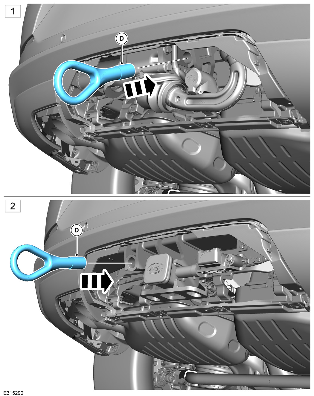
To use the recovery eye (D), remove the tow cover and screw and install the recovery eye to the towbar beam as illustrated above. When the recovery eye is not required store it in the foam tray under the loadspace floor. For more information refer to Owner's Handbook 'Vehicle Recovery'.

45
WARNING
  • See vehicle handbook for model specific trailer mass and nose load limits.

Inspect the operation of the trailer or bike carrier lamps and the vehicle lamps. Both trailer/bike carrier and vehicle lamps must be synchronised.

46
NOTE
  • Motor vehicle data, Deployable towbar.
NOTE
  • Motor vehicle data, NAS receiver towbar.
NOTE
  • Motor vehicle data, Australian receiver towbar.

Motor Vehicle Data sheets.

Description Specifications
Type 6467
D-value 17.2
Vertical coupling load 350kg
Coupling class A50-X
Manufacturer Brink Towing Systems B.V.
Model application Range Rover
EC-type approval number E11*55R01/08*11598*00
Maximum trailer weight 3500kg
Description Specifications
Type 6588
D-value 17.7
Vertical coupling load 350kg
Coupling class C50
Manufacturer Brink Towing Systems B.V.
Model application Range Rover
EC-type approval number N/A
Maximum trailer weight 3750kg
Description Specifications
Type 6589
D-value 17.7
Vertical coupling load 350kg
Coupling class C50
Manufacturer Brink Towing Systems B.V.
Model application Range Rover
EC-type approval number N/A
Maximum trailer weight 3750kg
© Land Rover 2016