LAND ROVER ACCESSORY FITTING INSTRUCTIONS

VEHICLE :
PART NO :
KEYWORD :

LAND ROVER

RANGE ROVER

FIXED SIDE STEPS - NON-ELECTRIC VEHICLES

VPLKFSS001 / VPLKFSS002 / VPLKP0493 / VPLKP0533 / VPLKP0496 / VPLKP0495 / VPLKP0494 / VPLKP0498 / VPLXP0513 / VPLKP0491

FITTING INSTRUCTION

WARNING
  • Accessories which are not correctly installed can be dangerous. Read the instructions carefully prior to ordering and installation to make sure this accessory is applicable to your variant of vehicle. Comply with instructions at all times. If in doubt, contact your nearest approved retailer.
Accessory Kits Vehicle Variant Part Number
Fixed Side Steps - Bright Short Wheel Base - (SWB) VPLKFSS001
Fixed Side Steps - Black Short Wheel Base - (SWB) VPLKFSS002

Jacking Points (Bill of Materials)

NOTE
  • Kits 'VPLKP0492' does not come with clips (A2) and (A3). These must be ordered separately (see section 'Additional parts if required') for clip part numbers and quantity.
Accessory Kits Vehicle Variant Replacement Service Part Number
Jacking Points Short Wheel Base - (SWB) VPLKP0493
Jacking Points - with extra clips Short Wheel Base - (SWB) VPLKP0533

Fixed Side Step - Brackets (Bill of Materials)

Accessory Kits Vehicle Variant Replacement Service Part Number
Fixed Side Step - Brackets - LH Short Wheel Base - (SWB) VPLKP0496
Fixed Side Step - Brackets - RH Short Wheel Base - (SWB) VPLKP0495

Deployable Side Step Board (Bill of Materials)

NOTE
  • Only 1 side step board comes in the replacement kit. If you require 2 then order 2 kits.
  • Older and newer parts numbers maybe present for the same item. Both are good to order and install depending on stock levels.
Accessory Kits Vehicle Variant Replacement Service Part Number
Deployable Side Step Board - Bright Short Wheel Base - (SWB) VPLKP0494
Deployable Side Step Board - Black Short Wheel Base - (SWB) VPLKP0498
Deployable Side Step Board - Black Short Wheel Base - (SWB) VPLXP0513

Side Step - Strip Protection (Bill of Materials)

Accessory Kits Vehicle Variant Replacement Service Part Number
Side Step - Strip Protection Short Wheel Base - (SWB) VPLKP0491

Additional parts required (Bill of Materials)

NOTE
  • If damaged or lost the following parts can be ordered separately.
  • Clips (A2) and (A3) must be ordered separately if you have ordered 'Jacking Points kits' 'VPLKP0493'. Number of clips required are shown in the table below.
Bill Of Materials Replacement Service Part Number Quantity
(A2) Trim Clips LR032984 x4
(A3) Trim Lantern Clips LR112137 x28

Warnings / Cautions / Notes / Tooling and Equipment

WARNING
  • Make sure to wear suitable personal protective equipment when cutting / drilling parts.
CAUTION
  • Installing side steps will affect the off-road capability of the vehicle.
  • When discarding parts do so in an environmentally responsible manner making sure all local laws are adhered to.
NOTE
  • If you are installing 'Mud Flaps' with the 'Side Steps' then they must be installed after the 'Side Steps' are installed.
  • This procedure contains illustrations for left side components, right side components are similar.
Tooling and Equipment
Torque Wrench
Socket Set
Torx Set
Allen key Socket Set
Trim Removal Tool
Oscillator cutting tool
Fitting Instruction
1

Open all doors and raise and support the vehicle.

  • Log into TOPIX and enter your 17 character 'Vehicle Identification Number' and navigate to 'Workshop Manual' section '100-02 Jacking and Lifting'.
2
NOTE
  • Repeat this step on the other side of the vehicle.

If installed to your vehicle, partially remove the front mud flap.

  1. Remove front wheel. Log into TOPIX and enter your 17 character 'Vehicle Identification Number' and navigate to 'Workshop Manual' section '204-04 Wheel and Tires / Wheel and Tire'.
  2. Remove mud flap fixings for access to the front wheel arch liner fixings later.
3

Remove the transmission undershield.

  • Log into TOPIX and enter your 17 character 'Vehicle Identification Number' and navigate to 'Workshop Manual' section 501-02 Front End Body Panels / Transmission Undershield'.
4
NOTE
  • Repeat this step on the other side of the vehicle.

Remove the jacking point cover.

  1. Remove clip (white arrow).
  2. Remove fixing.
5
NOTE
  • Repeat this step on the other side of the vehicle.

Remove the rear air deflector.

  • Remove x2 fixings.
6

Remove the rear-left and right undershields.

  • Log into TOPIX and enter your 17 character 'Vehicle Identification Number' and navigate to 'Workshop Manual' section 501-02 Front End Body Panels / Left Undershield'.
  • Log into TOPIX and enter your 17 character 'Vehicle Identification Number' and navigate to 'Workshop Manual' section 501-02 Front End Body Panels / Right Undershield'.
7
NOTE
  • Repeat this step on the other side of the vehicle.

Remove the rear rocker panel moulding.

  • Log into TOPIX and enter your 17 character 'Vehicle Identification Number' and navigate to 'Workshop Manual' section '501-08: Exterior Trim and Ornamentation / Rear Rocker Panel Moulding'.
8
NOTE
  • Repeat this step on the other side of the vehicle.

Remove the front rocker moulding.

  • Log into TOPIX and enter your 17 character 'Vehicle Identification Number' and navigate to 'Workshop Manual' section '501-08: Exterior Trim and Ornamentation / Front Rocker Panel Moulding'.
9
NOTE
  • Repeat this step on the other side of the vehicle.

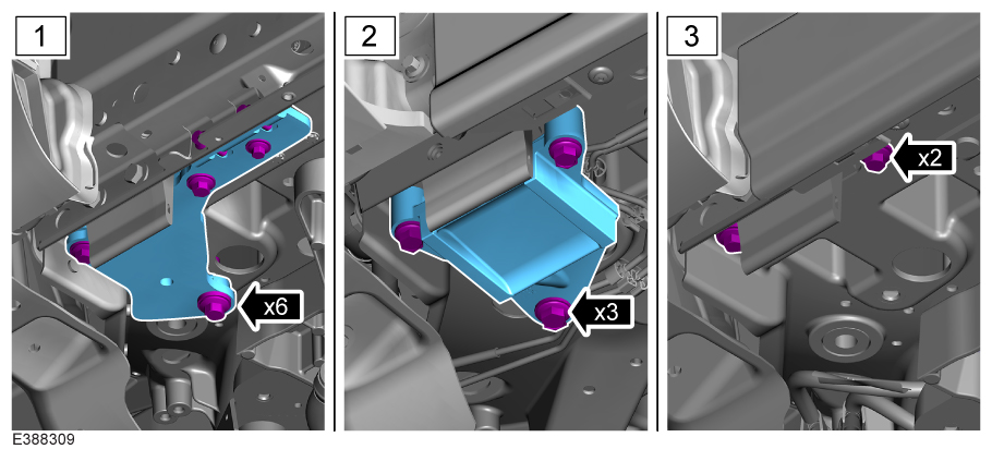
Depending on vehicle variant, you may be required to remove any fixings or front mounting brackets in the area under the removed jacking point cover.

  • Variant 1 = Remove x6 fixings and mounting bracket.
  • Variant 2 = Remove x3 fixings and mounting bracket.
  • Variant 3 = Remove x2 fixings.
10
NOTE
  • Repeat this step on the other side of the vehicle.

Removing the body harness blanking plug.

  1. Locate and unclip the body harness blanking plug from underneath the vehicle, located near the rear wheel.
  2. Remove the blanking plug from the connector.
11
NOTE
  • Repeat this step on the other side of the vehicle.

Replacing blanking connector clip.

  1. Remove the existing clip from the blanking connector and discard.
  2. Install new clip (E1) onto the blanking connector.
12
NOTE
  • Repeat this step on the other side of the vehicle.

Install the blanking connector with clip back onto the vehicle harness connector.

13
NOTE
  • Repeat this step on the other side of the vehicle.

Modify the jacking point cover.

  1. Identify the cut guide line. Paint over the cut guide lines to make the cut guide lines clearer.
  2. Use a suitable tool to cut the illustrated section.
  3. Discard the removed blue section.
14

Modify the transmission undershield.

  1. Identify both cut guide lines. Paint over the cut guide lines to make them clearer if required.
  2. Use a suitable tool to cut the illustrated sections.
  3. Discard the removed blue section.
15
NOTE
  • Repeat this step on the other side of the vehicle.

Modify the rear undershield.

  1. Using the existing cut guide line on the undershield as a guide. Measure and mark the remaining cut line as illustrated. Paint over the cut guide lines to make them clearer if required.
  2. Use a suitable tool to cut the illustrated section.
  3. Discard the removed blue section.
16

Identify which 'Jacking Point' is required for each side of the vehicle, as there may be two different types (left or right side).

Bill Of Materials Part Number Quantity
Front Jacking Point (A) M8EM-101E60-AC x2
Rear LH Jacking Point (B) M8EM-101E62-BD x1
Rear RH Jacking Point (B) M8EM-101E62-AD x1
Rear LH Connector Bracket (C) M8EM-112B19-BB x1
Rear RH Connector Bracket (C) M8EM-112B18-FB x1
17
NOTE
  • Repeat this step on the other side of the vehicle.

Jacking point installation check.

  1. The jacking point cutouts must align with the Self Piercing Rivet (SPR) on the body (arrowed).
  2. Inspect each jacking point to make sure it sits flush against the vehicle body floor panel and sill flange.
  3. Verify correct installation at all four corners.
18
NOTE
  • Repeat this step on the other side of the vehicle.

Installing front jacking point (A).

  1. Install, but do not fully tighten the vertical fixing (A1) first.
  2. Install, but do not fully tighten the remaining x2 fixings (A1).
19
NOTE
  • Repeat this step on the other side of the vehicle.

Installing the front jacking point (A) fully.

  1. Fully tighten the vertical fixing (A1) first. Torque: 24Nm
  2. Fully tighten the remaining x2 fixings (A1). Torque: 24Nm
20
NOTE
  • Repeat this step on the other side of the vehicle.

Installing jacking point (B) and the rear bracket (C).

  1. Install, but do not fully tighten the vertical fixing (A1) first.
  2. Install, but do not fully tighten the remaining x2 fixings (A1).
21
NOTE
  • Repeat this step on the other side of the vehicle.

Installing the front jacking point (B) fully.

  1. Fully tighten the vertical fixing (A1) first. Torque: 24Nm
  2. Fully tighten the remaining x2 fixings (A1). Torque: 24Nm
22
NOTE
  • Repeat this step on the other side of the vehicle.

Install the harness connector.

  • Install the harness connector with the new blanking connector to the rear jacking point bracket (C).
23
NOTE
  • Repeat this step on the other side of the vehicle.

Install the front rocker panel moulding, replacing any broken clips with clips (A3).

  • Log into TOPIX and enter your 17 character 'Vehicle Identification Number' and navigate to 'Workshop Manual' section '501-08: Exterior Trim and Ornamentation / Front Rocker Panel Moulding'.
24
NOTE
  • Repeat this step on the other side of the vehicle.

Install the rear rocker panel moulding, replacing any broken clips with clips (A2) and (A3).

  • Log into TOPIX and enter your 17 character 'Vehicle Identification Number' and navigate to 'Workshop Manual' section '501-08: Exterior Trim and Ornamentation / Rear Rocker Panel Moulding'.
25

Identify which side step bracket is required for each side of the vehicle, as there may be two different types (left or right side).

Bill Of Materials Part Marking Quantity
Front Fixed Side Step Bracket LH (D) B2552 x1
Front Fixed Side Step Bracket RH (D) B2554 x1
Rear Fixed Side Step Bracket LH (E) B2747 x1
Rear Fixed Side Step Bracket RH (E) B2748 x1
26
NOTE
  • Repeat this step on the other side of the vehicle.

Install the front fixed side step brackets (D). Observe the location identifier 'L/F' (left side front) or 'R/F' (right side front) on the brackets.

  1. Install, but do not fully tighten x2 fixings (D1).
  2. Install, but do not fully tighten fixing (D2).
27
NOTE
  • Repeat this step on the other side of the vehicle.

Install the rear fixed side step brackets (E). Observe the location identifier 'L/R' (left side rear) or 'R/R' (right side rear) on the brackets.

  • Install, but do not fully tighten x3 fixings (D1).
28
NOTE
  • Repeat this step on the other side of the vehicle.

Gap inspection.

  • Prior to installing the side (F), inspect that there is an even gap between the metal finisher and the rubber step part on the side step. Gap must be no more than 1.75mm for the top gap.
29
NOTE
  • Repeat this step on the other side of the vehicle.

Install the closure strip (G) to the step. Make sure the closure strip is in the correct orientation.

  1. Offer up the closure strip to the step. Make sure the sliding T fixings (shown in green) is positioned in the closure strip cutout spaces.
  2. Fasten with x2 fixings (G2). Make sure the rubber closure strip is not distorted when tightening the fixings.
30
NOTE
  • Repeat this step on the other side of the vehicle.

Install clips (G1) to the closure strip.

  • Install clips between the fixed side steps (F) and closure strip (G) making sure the clips are fully seated in the channel and using the clip spacing measurements as a guide.
31
NOTE
  • Repeat this step on the other side of the vehicle.

Install the side step (F).

  1. Make sure the T-nut on the step (green part in illustration), is aligned with the holes in the front and rear brackets using a suitable guide tool.
  2. Install, but do not fully tighten x2 fixings (F1) to install the side step onto the front bracket.
  3. Install, but do not fully tighten x2 fixings (F1) to install the side step onto the rear bracket.
32
NOTE
  • Repeat this step on the other side of the vehicle.

Position the side step.

  • Slide the side step to the furthest most rearward position.
33
NOTE
  • Repeat this step on the other side of the vehicle.

Inspect side step and bracket position before final tightening of fixings.

  • Make sure the contact faces of the side step bracket and step are flush with each other. If the step and bracket are not flush then the holes will not correctly line up and there will be a risk of cross-threading the fixings.
34
NOTE
  • Repeat this step on the other side of the vehicle.

Tighten all bracket to side step fixings.

  • Fully tighten x4 side step fixings (F1). Mark fixings when the recommended torque has been achieved. Torque: 10Nm
35
CAUTION
  • Tightening of fixing sequence must be followed. A Diagnostic Trouble Codes (DTC) 'Obstruction Error' may show if sequence is not followed.
NOTE
  • Both 'Deployable' and 'Fixed Side Steps' shown in graphic. Tightening sequence is the same.
  • Repeat this step on the other side of the vehicle.

Fully tighten the side step bracket fixings in the sequence shown.

  • 1-5: M10 Torque: 60Nm
  • 6: M12 Torque: 70Nm
36

Install the modified rear-left and right undershields.

  • Log into TOPIX and enter your 17 character 'Vehicle Identification Number' and navigate to 'Workshop Manual' section 50102 Front End Body Panels / Left Undershield'.
  • Log into TOPIX and enter your 17 character 'Vehicle Identification Number' and navigate to 'Workshop Manual' section 501-02 Front End Body Panels / Right Undershield'.
37
NOTE
  • Repeat this step on the other side of the vehicle.

Install the modified jacking point cover.

  1. Install clip (white arrow).
  2. Install fixing. Torque: 5Nm
38

Install the modified transmission undershield.

  • Log into TOPIX and enter your 17 character 'Vehicle Identification Number' and navigate to 'Workshop Manual' section 501-02 Front End Body Panels / Transmission Undershield'.
39
NOTE
  • Repeat this step on the other side of the vehicle.

Install front mud flap if originally removed.

  1. Install mud flap original fixings. Torque: 6Nm
  2. Install front wheel. Log into TOPIX and enter your 17 character 'Vehicle Identification Number' and navigate to 'Workshop Manual' section '204-04 Wheel and Tires / Wheel and Tire'.
40

Lower the vehicle and close all doors and inspect 'Fixed Side Steps' before customer handover.

© Land Rover 2016