LAND ROVER ACCESSORY FITTING INSTRUCTIONS

VEHICLE :
PART NO :
KEYWORD :

LAND ROVER

RANGE ROVER

TOWING SYSTEMS (MECHANICAL ONLY)

VPLKT0325 / VPLKT0326 / VPLKT0327 / LR175639 / LR155009 / LR175640 / LR155010

FITTING INSTRUCTION

WARNING
  • Accessories which are not correctly installed can be dangerous. Read the instructions carefully prior to installation. Comply with the instructions at all times. If in doubt, contact your nearest approved retailer.
  • Any parts discarded must be recycled in a environmentally responsible manner making sure all local laws are adhered to.

Deployable Towbar - VPLKT0327 (Bill of Materials)

CAUTION
  • Under no circumstances is the motor to be removed from the towbar armature when being replaced. The complete armature assembly needs to be returned otherwise any claim will be rejected.
NOTE
  • Inspect contents of kits to make sure that all the parts shown in the BOM image below are present.
  • The tow cover (C) does not come in the towbar kit and must be ordered separately, or as part of the virtual kitting part number.
  • For motor vehicle data, see sheet at the end of these instructions.
Bill Of Materials Replacement Service Part Number
(A) Towbar - x1 VPLKT0327
(A1) Bolt - M12x55 - x4 W780893
(A2) Bolt - M14x55 - x6 W713336
(B) Recovery Eye - x1 VPLKT0327
(C) Tow Cover - Indus Gray - x1 LR175639
(C) Tow Cover - Graphite Atlas - x1 LR155009
(D) Label (Australian market only) x1 VPLKT0327

NAS Towbar - VPLKT0326 (Bill of Materials)

NOTE
  • Inspect contents of kits to make sure that all the parts shown in the BOM image below are present.
  • The tow cover (C) does not come in the towbar kit and must be ordered separately, or as part of the virtual kitting part number.
  • For motor vehicle data, see sheet at the end of these instructions.
Bill Of Materials Replacement Service Part Number
(A) Towbar - x1 VPLKT0326
(A1) Bolt - M12x55 - x4 W780893
(A2) Bolt - M14x55 - x6 W713336
(B) Recovery Eye - x1 VPLKT0326
(C) Tow Cover - Indus Gray - x1 LR175640
(C) Tow Cover - Graphite Atlas - x1 LR155010

Australian Towbar - VPLKT0325 (Bill of Materials)

NOTE
  • Inspect contents of kits to make sure that all the parts shown in the BOM image below are present.
  • The tow cover (C) does not come in the towbar kit and must be ordered separately, or as part of the virtual kitting part number.
  • For motor vehicle data, see sheet at the end of these instructions.
Bill Of Materials Replacement Service Part Number
(A) Towbar - x1 VPLKT0325
(A1) Bolt - M12x55 - x4 W780893
(A2) Bolt - M14x55 - x6 W713336
(B) Recovery Eye - x1 VPLKT0325
(C) Tow Cover - Indus Gray - x1 LR175640
(C) Tow Cover - Graphite Atlas - x1 LR155010

Tooling

Tooling
Trim Removal Tool
Ratchet
Socket - 10, 15, 18mm
Torque Wrench - 50Nm to 200Nm
4 Pillar Vehicle Lift
Jaguar Land Rover Approved Diagnostic Equipment
REMOVAL INSTRUCTIONS
1

The towbar electrics for your specific towbar must be installed first. Refer to there separate instructions if not installed.

  • Towing Electrics (5 Seat) - LR158164 / LR158165 / VPLKT0318 / VPLYT0295 / VPLKV0133 / FN106042
  • Towing Electrics (7 Seat) - LR158167 / LR158166 / VPLKT0318 / VPLYT0295 / VPLKV0132 / FN106042 / LR029806
2

Open upper and lower tailgates.

3
NOTE
  • This step requires the aid of another person.
  • Make sure to retain all fixings.
  • Tools to remove the rear bumper are not covered in the 'Tooling'.
  • When fitting towing and rear mudflaps, it is recommended to install towing first followed by the rear mudflaps. If rear mudflaps are already installed, see to next step.

Remove rear bumper.

  • For additional information, please refer to the official Workshop Manual. Rear Bumper Cover (501-19 Bumpers)
4
NOTE
  • This step is only for vehicles with rear mudflaps installed.

If the rear mudflaps are already installed, the mudflaps will remain on the rear bumper when it is removed, the x2 fixings are to be removed only.

5

Close both upper and lower tailgates.

6

Raise and support vehicle on a 4 pillar ramp.

  • For additional information, please refer to the official Workshop Manual. Jacking and Lifting (100-02 Jacking and Lifting)
7
WARNING
  • Observe due care when working near a hot exhaust system. Make sure the exhaust system is supported at all times.
NOTE
  • This step contains some variation in the illustration depending on the vehicle specification, but the essential information is always correct.

Drop rear exhaust sufficiently enough to gain access to the rear bumper armature fixings.

  • Diesel 3.0L For additional information, please refer to the official Workshop Manual. Rear Silencer (309-00 Exhaust System - INGENIUM I6 3.0L Diesel)
  • Petrol 3.0L For additional information, please refer to the official Workshop Manual. Exhaust System (309-00 Exhaust System - INGENIUM I6 3.0L Petrol)
  • Petrol 4.4L For additional information, please refer to the official Workshop Manual. Exhaust System (309-00 Exhaust System - INGENIUM I6 3.0L Petrol)
8

Remove rear bumper armature and discard. For additional information, please refer to the official Workshop Manual. Rear Armature (501-19 Bumpers)

9

Unclip x2 harness connectors and clips from bumper bracket.

10

Disconnect keyless entry module connector.

11
WARNING
  • Observe due care when working near a hot exhaust system.

Remove x8 fixings to remove the lower bumper bracket and heat shield. Do 'Not' discard the fixings.

12

Remove x6 fixings to remove the upper bumper bracket. Do 'Not' discard the fixings.

Fitting Instruction
1
NOTE
  • 'Electrical Deployable Towing' harness shown. 'NON - Electrical Deployable Towing' harness is similar.

Secure the towing harness (already installed) to the vehicle body with x4 or x6 clips depending on harness variant.

2

Install x6 fixings to secure the upper bumper bracket to the vehicle.

3

Install x8 fixings to secure the lower bumper bracket and heat shield to the vehicle.

4

Reconnect harness connector to keyless entry module. An audible click will be heard when the connector has fully engaged.

5

Reconnect harness connectors (x2) and clip the connector to the bumper bracket. An Audible click will be heard when the connector has fully engaged.

6

Detach the towbar electrical connectors from the towbar beam. Clip the x2 towbar electrical connectors into the towbar beam as illustrated.

7
WARNING
  • Heavy component, risk of injury. Two persons are required for this step. When in position, one person will need to hold it in place while the other installs the fixings in the next step.

Install towbar beam (A) into body.

8
CAUTION
  • Tightening sequence must be followed as illustrated below.

Hand start fixings (A1) and then fully tighten in the sequence shown above. Position 1 illustrated in the above image is the datum fixing.

  • Torque: 80Nm + 150º
9

Hand start the remaining x4 fixings (A2) and fully tighten in the sequence shown above.

  • Torque: 70Nm + 240º
10
NOTE
  • Deployable towbar shown. NAS / Australian and Detachable towbars will only have the x2 connections on the right side.

Connect towbar electrics (x3) connections. An audible click will be heard when the connectors are fully engaged.

11
NOTE
  • This step contains some variation in the illustration depending on the vehicle specification, but the essential information is always correct.

Install rear silencer.

  • Diesel 3.0L For additional information, please refer to the official Workshop Manual. Rear Silencer (309-00 Exhaust System - INGENIUM I6 3.0L Diesel)
  • Petrol 3.0L For additional information, please refer to the official Workshop Manual. Exhaust System (309-00 Exhaust System - INGENIUM I6 3.0L Petrol)
  • Petrol 4.4L For additional information, please refer to the official Workshop Manual. Exhaust System (309-00 Exhaust System - INGENIUM I6 3.0L Petrol)
12

Lower the vehicle on the 4 pillar ramp.

13

Open upper and lower tailgates.

14
NOTE
  • Detachable tow cover shown. Other variants similar.
  • This step requires the aid of another person.

Install rear bumper and discard the non-towbar cover and install the new towbar cover (C) for your specific towbar. Re-use the fixings for the towbar cover.

  • For additional information, please refer to the official Workshop Manual. Rear Bumper Cover (501-19 Bumpers)
15
NOTE
  • Australian Market 'ONLY'.
  • Label must be legible after installation.

Attach label (D) to drivers door in the area approximately shown. Surface should be flat and smooth and the label must not be installed over holes or rounded edges. Label must be positioned to avoid contact with other objects that may lead to premature wear.

16

For install of the NAS and Australian towbar hitch to the towbar.

  • For additional information, please refer to the official Workshop Manual. Towbar Hitch (102-05 Towing)
17

Close upper and lower tailgates.

18
WARNING
  • Inspect the vehicle handbook for model specific trailer mass and nose load limits.

Inspect the operation of the trailer or bike carrier lamps and the vehicle lamps. Both trailer/bike carrier and vehicle lamps must be synchronised.

19
WARNING
  • If you have the deployable towbar installed, make sure the towbar is in the stowed position using the loadspace switch pack or PIVI screen.
  • If you have the NAS / Australian or Detachable towbar installed, make sure the towbar hitch are removed and securely stored in the loadspace.

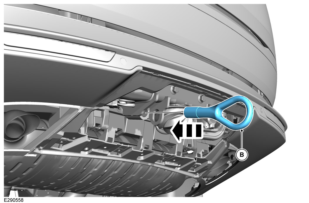
To use the recovery eye (B), remove the tow cover and screw and install the recovery eye (B) to the towbar beam as illustrated above. When the recovery eye is not required, store it in the foam tray under the loadspace floor. For more information refer to Owner's Handbook 'Vehicle Recovery'.

20

Motor Vehicle Data sheets.

Motor vehicle data, deployable towbar Specifications
Type 6467
D-value 17.2
Vertical coupling load 350kg
Coupling class A50-X
Manufacturer Brink Towing Systems B.V.
Model application Range Rover
EC-type approval number E11*55R01/08*11598*00
Maximum trailer weight 3500kg
Motor vehicle data, NAS towbar Specifications
Type 6588
D-value 17.7
Vertical coupling load 350kg
Coupling class A50-X
Manufacturer Brink Towing Systems B.V.
Model application Range Rover
EC-type approval number N/A
Maximum trailer weight 3750kg
Motor vehicle data, Australian towbar Specifications
Type 6589
D-value 17.7
Vertical coupling load 350kg
Coupling class C50
Manufacturer Brink Towing Systems B.V.
Model application Range Rover
EC-type approval number N/A
Maximum trailer weight 3750kg
© Land Rover 2016