LAND ROVER ACCESSORY FITTING INSTRUCTIONS

VEHICLE :
PART NO :
KEYWORD :

LAND ROVER

DEFENDER

FIXED SIDE STEPS AND SIDE TUBES

VPLEP0391 / VPLEP0392 / VPLEP0433 / VPLEP0434 / VPLEP0521 / VPLEP0522 / VPLEP0524 / VPLEP0525 / VPLEP0513 / VPLEP0514 / LR112137

FITTING INSTRUCTION

WARNING
  • Accessories which are not correctly installed can be dangerous. Read the instructions carefully prior to ordering and installation to make sure this accessory is applicable to your variant of vehicle. Comply with instructions at all times. If in doubt, contact your nearest approved retailer.
Kits Required Part Number Superseded By
Fixed Side Steps - 90 VPLEP0391 VPLEP0524
Fixed Side Steps (Black) - 90 VPLEP0514
Fixed Side Steps - 110/130 VPLEP0392 VPLEP0525
Fixed Side Steps (Black) - 110/130 VPLEP0513
Side Tubes - 90 VPLEP0433 VPLEP0522
Side Tubes - 110/130 VPLEP0434 VPLEP0521
Trim Clip LR112137

Fixed Side Steps for Defender 90 (Bill of Materials)

NOTE
  • If missing, lost or damaged, replacement fixings can be ordered separately. (See table below)
Fixings Replacement Part Numbers
(D) M10x60 Bolt LR152410
(E) M8x28 Screw LR135788
(F) M6x23 Screw LR141748

Fixed Side Steps for Defender 110/130 (Bill of Materials)

NOTE
  • If missing, lost or damaged, replacement fixings can be ordered separately. (See table below)
Fixings Replacement Part Numbers
(D) M10x60 Bolt LR152410
(E) M8x28 Screw LR135788
(F) M6x23 Screw LR141748

Side Tubes for Defender 90 (Bill of Materials)

NOTE
  • If missing, lost or damaged, replacement fixings can be ordered separately. (See table below)
Fixings Replacement Part Numbers
(D) M10x60 Bolt LR152410
(E) M8x28 Screw LR135788
(F) M6x23 Screw LR141748

Side Tubes for Defender 110/130 (Bill of Materials)

NOTE
  • If missing, lost or damaged, replacement fixings can be ordered separately. (See table below)
Fixings Replacement Part Numbers
(D) M10x60 Bolt LR152410
(E) M8x28 Screw LR135788
(F) M6x23 Screw LR141748

Trim Clips

NOTE
  • Trim clips - LR112137 will need to be ordered as required if they are damaged during removal of the exterior body trims. The maximum quantity that may be required is x30 for both sides of the vehicle.
REMOVAL INSTRUCTIONS
1
WARNING
  • If a suitable 4 post lift is not available then refer to the wheel changing section of the owner's handbook.
CAUTION
  • Make sure to use the front and rear subframe jacking points.
NOTE
  • Make sure the ramp legs are positioned so they do not obstruct the fixed side step or side tube installation location.

Raise and support the vehicle on a suitable 4 post lift. The front and rear subframe jacking points must be used. Do not use the sill jacking points. For additional information, please refer to the official Workshop Manual. Jacking and Lifting (100-02 Jacking and Lifting)

  • If a suitable 4 post lift is not available then refer to the wheel changing section of the Owner's Handbook.
2
CAUTION
  • Clips may be damaged during removal. Replace clips if they are damaged with clips (H).
NOTE
  • Make sure that the x4 clips remain on the front fender moulding.
  • Remove the front mudflaps if installed to the vehicle.

Remove front fender mountings on both sides of the vehicle.

  • For additional information, please refer to the official Workshop Manual. Front Fender Moulding (501-08)
3
CAUTION
  • Clips may be damaged during removal. Replace clips if they are damaged with clips (H).

Remove rocker panel on both sides of the vehicle.

  • For Defender 90 vehicles see For additional information, please refer to the official Workshop Manual. Rocker Panel Moulding - 90 (501-08)
  • For Defender 110/130 vehicles see For additional information, please refer to the official Workshop Manual. Rocker Panel (501-08)
4
NOTE
  • Defender 110/130 shown. Defender 90 has less fixings to remove on the x2 side undershields.

Remove transmission shield and side undershields.

  • For additional information, please refer to the official Workshop Manual. Left Undershield (501-02)
  • For additional information, please refer to the official Workshop Manual. Right Undershield (501-02)
5
NOTE
  • Complete step for Defender 110/130.
  • The cut guide lines are different for the left side rocker panel and the right side rocker panel.

Identify the cut guide lines on the left side rocker panel.

  • Paint over the cut guide lines to make the cut guide lines clearer. This will help when they are cut.
6
NOTE
  • Complete step for Defender 90.
  • The cut guide lines are different for the left side rocker panel and the right side rocker panel.

Identify the cut guide lines on the left side rocker panel.

  • Paint over the cut guide lines to make the cut guide lines clearer. This will help when they are cut.
7
NOTE
  • Complete step for Defender 110/130.
  • The cut guide lines are different for the left side rocker panel and the right side rocker panel.

Identify the cut guide lines on the right side rocker panel.

  • Paint over the cut guide lines to make the cut guide lines clearer. This will help when they are cut.
8
NOTE
  • Complete step for Defender 90.
  • The cut guide lines are different for the left side rocker panel and the right side rocker panel.

Identify the cut guide lines on the right side rocker panel.

  • Paint over the cut guide lines to make the cut guide lines clearer. This will help when they are cut.
9
WARNING
  • Make sure to wear suitable personal protective equipment.
CAUTION
  • Make sure to follow the cut guide lines as illustrated.
NOTE
  • Defender 110/130 shown. Same process for Defender 90.

Use suitable tooling to cut the illustrated sections from the left side rocker panel. Discard the removed sections.

  1. Drill holes at the illustrated locations.
  2. Use the cut guide lines on the rocker panel.
10
WARNING
  • Make sure to wear suitable personal protective equipment.
CAUTION
  • Make sure to follow the cut guide lines as illustrated.
NOTE
  • Defender 110/130 shown. Same process for Defender 90.

Use suitable tooling to cut the illustrated sections from the right side rocker panel. Discard the removed sections.

  1. Drill holes at the illustrated locations.
  2. Use the cut guide lines on the rocker panel.
11
NOTE
  • Left side rocker panel shown. Appearance of left side rocker is different to the right side rocker panel.
  • Defender 110/130 shown. Same process for Defender 90.

Position the left side rocker panel over the top of the left undershield as illustrated.

  • Use the holes in the rocker panel and the undershield to make sure there is accurate alignment.
12
CAUTION
  • Make sure to carefully mark the sections of the undershield that will be cut.
NOTE
  • Defender 110/130 shown. Same process for Defender 90.

Use the left side rocker panel as a template to define the x2 sections of the left undershield that will be cut, as illustrated.

  1. Make sure the holes in the rocker panel align with the matching holes in the undershield.
  2. Mark the cut guide lines on the undershield using the rocker panel as a template.
13
NOTE
  • Defender 110/130 shown. Same process for Defender 90.

Make sure the cut guide lines have a depth of 50 mm as illustrated.

14
WARNING
  • Make sure to wear suitable personal protective equipment.
NOTE
  • Defender 110/130 shown. Same process for Defender 90.

Use suitable tooling to cut the illustrated sections from the left undershield. Discard the removed sections.

15

Complete 'Steps 11 to 14' for the right side undershield using the right side rocker panel as a template.

16
NOTE
  • For ROW market vehicles only.

Remove and discard x1 fixing as illustrated on both sides of the vehicle.

17
NOTE
  • For ROW market vehicles only.

Remove and discard x1 fixing as illustrated on both sides of the vehicle.

18
NOTE
  • For NAS market vehicles only.

Remove and discard x2 fixing as illustrated on both sides of the vehicle.

19
NOTE
  • For NAS market vehicles only.

Remove and discard x1 fixing as illustrated on both sides of the vehicle.

Fitting Instruction
1

Follow the appropriate steps depending on the accessory that is being installed.

  • For installation of 'Fixed Side Steps' complete 'Steps 2 to 21'.
  • For installation of 'Side Tubes' complete 'Steps 22 to 42'.
2
NOTE
  • Side step brackets for Defender 90 will have the text "90" on the identifier label.
  • Side step brackets for Defender 110/130 will have the text "110" on the identifier label.

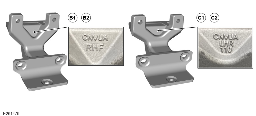
The side step brackets are individually labelled with the position on the vehicle they must be installed at (RHF, LHF, LHR, RHR).

  • Locate the identifier label on each bracket.
3
NOTE
  • Follow the appropriate steps depending on vehicle specification.

Install the side step brackets to the vehicle.

  • For Defender 110/130 complete 'Steps 4 to 6', then jump to and continue at 'Step 11'.
  • For Defender 90 complete 'Steps 7 to 10', then continue to 'Step 11'.
4
CAUTION
  • Complete step for all Defender 110/130 markets except for NAS.
  • Make sure the brackets are installed at the correct location on the vehicle. Observe the location identifier (LHF) or (RHF) on the brackets.

Install the 'front' side step brackets (B1) and (B2) to both sides of the vehicle.

  1. Install x2 fixings (D) and x2 spacers (G), but do not fully tighten.
  2. Install x2 fixings (E), but do not fully tighten.
5
CAUTION
  • Complete this step for Defender 110/130 NAS market only.
  • Make sure the brackets are installed at the correct location on the vehicle. Observe the location identifier (LHF) or (RHF) on the brackets.

Install the 'front' side step brackets (B1) and (B2) to both sides of the vehicle.

  1. Install x2 fixings (D), but do not fully tighten.
  2. Install x2 fixings (E), but do not fully tighten.
6
CAUTION
  • Complete this step for Defender 110/130.
  • Make sure the brackets are installed at the correct location on the vehicle. Observe the location identifier (LHR) or (RHR) on the brackets.

Install the 'rear' side step brackets (C1) and (C2) to both sides of the vehicle.

  1. Install x2 fixings (D), but do not fully tighten.
  2. Install x2 fixings (E), but do not fully tighten.
7
CAUTION
  • Complete this step for all Defender 90 markets except for NAS.
  • Make sure the brackets are installed at the correct location on the vehicle. Observe the location identifier (LHF) or (RHF) on the brackets.

Install the 'front' side step brackets (B1) and (B2) to both sides of the vehicle.

  1. Install x2 fixings (D) and x2 spacers (G), but do not fully tighten.
  2. Install x2 fixings (E), but do not fully tighten.
8
CAUTION
  • Complete this step for Defender 90 NAS market only.
  • Make sure the brackets are installed at the correct location on the vehicle. Observe the location identifier (LHF) or (RHF) on the brackets.

Install the 'front' side step brackets (B1) and (B2) to both sides of the vehicle.

  1. Install x2 fixings (D), but do not fully tighten.
  2. Install x2 fixings (E), but do not fully tighten.
9
CAUTION
  • Complete this step for all Defender 90 markets except for NAS.
  • Make sure the brackets are installed at the correct location on the vehicle. Observe the location identifier (LHR) or (RHR) on the brackets.

Install the 'rear' side step brackets (C1) and (C2) to both sides of the vehicle.

  1. Install x2 fixings (D) and the x2 spacers (G), but do not fully tighten.
  2. Install x2 fixings (E), but do not fully tighten.
10
CAUTION
  • Complete this step for Defender 90 NAS market only.
  • Make sure the brackets are installed at the correct location on the vehicle. Observe the location identifier (LHR) or (RHR) on the brackets.

Install the 'rear' side step brackets (C1) and (C2) to both sides of the vehicle.

  1. Install, but do not fully tighten the x2 fixings (D) and x1 spacer (G).
  2. Install, but do not fully tighten the x2 fixings (E).
11
CAUTION
  • Observe the hand symbol label on the side step bars.

Locate the hand symbol label on each of the side step bars.

  • The hand graphic points towards the front of the vehicle to help when installing the side step bars to vehicles with 90 wheelbase.
12
CAUTION
  • The side step bar must be installed to the correct side of the vehicle.
  • For Defender 90 vehicles take particular care as the handedness is not obvious. Observe the hand symbol label on the side step bars.
NOTE
  • This step requires the aid of another technician.
  • Defender 110/130 shown. Process is same for Defender 90.

Install the side step bar (A) to the brackets (B) and (C) using the x6 fixings (F), but do not fully tighten fixings.

  • Make sure the side step bar is installed to the correct side of the vehicle. The hand graphic on the side step bar must face towards the front of the vehicle.
  • Install, but do not fully tighten fixings (F).
13
CAUTION
  • Side step brackets may crack when fully tightened if they are not installed correctly.

Before fully tightening side step brackets, make sure there is no gap between the side step brackets and the outer vehicle sill. Then continue to the next step.

14
CAUTION
  • If tighten sequence is not followed, this could result in damage to the brackets.
NOTE
  • Defender 110/130 shown. Process is same for Defender 90.

Fully tighten the x4 fixings (E) as illustrated. Starting with the rear bracket first.

  1. Rear bracket - Tighten fixing (1) first and then fixing (2). Torque: 24Nm
  2. Front bracket - Tighten fixing (1) first and then fixing (2). Torque: 24Nm
15
CAUTION
  • Make sure 'Step 14' is completed. Failure to follow the tightening sequence will result in damage to the bracket.
  • Do not use a impact applicator.
NOTE
  • Defender 110/130 shown. Process is same for Defender 90.

Fully tighten the x4 fixings (D).

  • Torque: 64Nm
16
NOTE
  • This step requires the aid of another technician.
  • Defender 110/130 shown. Process is same for Defender 90.

Remove fixings (F) and remove the side step bar (A).

  • The undershields and rocker panels will need to be installed before the final install of the side step bar.
17

Repeat 'Steps 13 to 16' for the right side of the vehicle.

18

Install side undershields and transmission shield.

  • For additional information, please refer to the official Workshop Manual. Left Undershield (501-02)
  • For additional information, please refer to the official Workshop Manual. Right Undershield (501-02)
19

Install the rocker panel on both sides of the vehicle.

  • For Defender 90 vehicles see For additional information, please refer to the official Workshop Manual. Rocker Panel Moulding - 90 (501-08)
  • For Defender 110/130 vehicles see For additional information, please refer to the official Workshop Manual. Rocker Panel (501-08)
20

Install front fender mountings on both sides of the vehicle.

  • For additional information, please refer to the official Workshop Manual. Front Fender Moulding (501-08)
21
CAUTION
  • For Defender 90 vehicles, the side step bar must be installed to the correct side of the vehicle.
NOTE
  • Complete step for the installation of the fixed side steps.
  • This step requires the aid of another technician.

Install the side step bar (A) to the brackets (B) and (C) using fixings (F). Complete step on both sides of the vehicle.

  • For Defender 90, make sure the side step bar is installed to the correct side of the vehicle. The hand graphic on the side step bar must face towards the front of the vehicle.
  • Torque: 10Nm
22

For installation of 'Side Tubes' complete 'Steps 23 to 42'.

23
NOTE
  • Defender 110/130 front brackets have a rectangular notch and rear brackets have a oval notch.
  • Defender 90 front brackets have a rectangular notch and rear brackets have a triangular notch.

The side tube brackets are individually labelled with the position on the vehicle they must be installed at (FR, FL, RR, RL).

  • Locate the identifier label on each bracket.
  • The appearance of the arrowed notch is different between front brackets and rear brackets. The notch appearance also varies between Defender 110/130 and 90.
24
NOTE
  • Follow the appropriate steps depending on vehicle specification.

Install the side tube brackets to the vehicle.

  • For Defender 110/130 complete 'Steps 25 to 27' and then jump to and continue at 'Step 32'.
  • For Defender 90 complete 'Steps 28 to 31' and then continue to 'Step 32'.
25
CAUTION
  • Complete step for all Defender 110/130 markets except for NAS.
  • Make sure the brackets are installed at the correct location on the vehicle. Observe the location identifier (FL) or (FR) on the brackets.

Install the 'front' side tube brackets (B1) and (B2) to both sides of the vehicle.

  1. Install x2 fixings (D) and the x2 spacers (G), but do not fully tighten.
  2. Install x2 fixings (E), but do not fully tighten.
26
CAUTION
  • Complete this step only for Defender 110/130 NAS market vehicles.
  • Make sure the brackets are installed at the correct location on the vehicle. Observe the location identifier (FL) or (FR) on the brackets.

Install the 'front' side tube brackets (B1) and (B2) to both sides of the vehicle.

  1. Install x2 fixings (D), but do not fully tighten.
  2. Install x2 fixings (E), but do not fully tighten.
27
CAUTION
  • Complete this step for Defender 110/130.
  • Make sure the brackets are installed at the correct location on the vehicle. Observe the location identifier (RL) or (RR) on the brackets.

Install the 'rear' side tube brackets (C1) and (C2) to both sides of the vehicle.

  1. Install x2 fixings (D), but do not fully tighten.
  2. Install x2 fixings (E), but do not fully tighten.
28
CAUTION
  • Complete this step for all Defender 90 markets, except for NAS.
  • Make sure the brackets are installed at the correct location on the vehicle. Observe the location identifier (FL) or (FR) on the brackets.

Install the 'front' side tube brackets (B1) and (B2) to both sides of the vehicle.

  1. Install x2 fixings (D) and the x2 spacers (G), but do not fully tighten.
  2. Install x2 fixings (E), but do not fully tighten.
29
CAUTION
  • Complete this step for Defender 90 NAS market only.
  • Make sure the brackets are installed at the correct location on the vehicle. Observe the location identifier (FL) or (FR) on the brackets.

Install the 'front' side tube brackets (B1) and (B2) to both sides of the vehicle.

  1. Install x2 fixings (D), but do not fully tighten.
  2. Install x2 fixings (E), but do not fully tighten.
30
CAUTION
  • Complete this step for all Defender 90 markets except for NAS.
  • Make sure the brackets are installed at the correct location on the vehicle. Observe the location identifier (RL) or (RR) on the brackets.

Install the 'rear' side tube brackets (C1) and (C2) to both sides of the vehicle.

  1. Install x2 fixings (D) and x2 spacers (G), but do not fully tighten.
  2. Install x2 fixings (E), but do not fully tighten.
31
CAUTION
  • Complete this step for Defender 90 NAS market only.
  • Make sure the brackets are installed at the correct location on the vehicle. Observe the location identifier (RL) or (RR) on the brackets.

Install the 'rear' side tube brackets (C1) and (C2) to both sides of the vehicle.

  1. Install x2 fixings (D) and x1 spacer (G), but do not fully tighten.
  2. Install x2 fixings (E), but do not fully tighten.
32
CAUTION
  • Observe the hand symbol label on the side tubes.

Locate the hand symbol label on each of the side tubes.

  • The hand graphic points towards the front of the vehicle to help when installing the side tubes to vehicles with 90 or 110/130 wheelbase.
33
CAUTION
  • Install, but do not fully tighten fixings (F).
  • The side tube must be installed to the correct side of the vehicle.
  • For Defender 90 take particular care as the handedness is not obvious. Observe the hand symbol label on the side tubes.
NOTE
  • This step requires the aid of another technician.
  • Defender 110/130 shown. Process is same for Defender 90.

Install the side tube (A) to the brackets (B) and (C) using the x6 fixings (F).

  • Make sure the side tube is installed to the correct side of the vehicle. The hand graphic on the side tube must face towards the front of the vehicle.
  • Install, but do not fully tighten fixings (F).
34
CAUTION
  • Side step brackets may crack when fully tightened if they are not installed correctly.

Before fully tightening side tube brackets, make sure there is no gap between the side tube brackets and the outer vehicle sill. Then continue to the next step.

35
CAUTION
  • If tighten sequence is not followed, this could result in damage to the brackets.
NOTE
  • Defender 110/130 shown. Process is same for Defender 90.

Fully tighten the x4 fixings (E) as illustrated. Starting with the rear bracket first.

  1. Rear bracket - Tighten fixing (1) first and then fixing (2). Torque: 24Nm
  2. Front bracket - Tighten fixing (1) first and then fixing (2). Torque: 24Nm
36
CAUTION
  • Make sure 'Step 35' is completed. Failure to follow the tightening sequence will result in damage to the bracket.
  • Do not use a impact applicator.
NOTE
  • Defender 110/130 shown. Process is same for Defender 90.

Fully tighten the x4 fixings (D).

  • Torque: 64Nm
37
NOTE
  • This step requires the aid of another technician.
  • Defender 110/130 shown. Process is same for Defender 90.

Remove fixings (F) and remove the side tube (A).

  • The undershields and rocker panels will need to be installed before the final install of the side tubes.
38

Repeat 'Steps 34 to 37' for the right side of the vehicle.

39

Install side undershields and transmission shield.

  • For additional information, please refer to the official Workshop Manual. Left Undershield (501-02)
  • For additional information, please refer to the official Workshop Manual. Right Undershield (501-02)
40

Install the rocker panel on both sides of the vehicle.

  • For Defender 90 vehicles see For additional information, please refer to the official Workshop Manual. Rocker Panel Moulding - 90 (501-08)
  • For Defender 110/130 vehicles see For additional information, please refer to the official Workshop Manual. Rocker Panel (501-08)
41

Install front fender mountings on both sides of the vehicle.

  • For additional information, please refer to the official Workshop Manual. Front Fender Moulding (501-08)
42
CAUTION
  • Side tubes must be installed to the correct side of the vehicle.
NOTE
  • Complete step for the installation of the side tubes.
  • This step requires the aid of another technician.

Install the side tube (A) to the brackets (B) and (C) using fixings (F). Complete step on both sides of the vehicle.

  • Make sure the side tube is installed to the correct side of the vehicle. The hand graphic on the side tube must face towards the front of the vehicle.
  • Torque: 10Nm
© Land Rover 2016