LAND ROVER ACCESSORY FITTING INSTRUCTIONS

VEHICLE :
PART NO :
KEYWORD :

LAND ROVER

DEFENDER

CROSS BARS - 90

VPLER0179 / VPLLE0022

FITTING INSTRUCTION

WARNING
  • Accessories which are not correctly installed can be dangerous.
  • Before ordering and installing the accessory, you must read all the instructions. The correct accessory / part must be ordered for you variant of the vehicle.
  • You must follow all instructions. If in doubt, contact your nearest approved retailer.
Kits Required Part Number Superseded by
Cross Bars - Defender 90 VPLER0179 VPLLE0022

Cross Bars (Bill of Materials)

WARNING
  • Older part numbers are still applicable if superseded part numbers are not used from the table above.
Bill Of Materials Quantity Replacement Service Part Number
(A) Key x4
(B) Front Cross Bar x1
(C) Rear Cross Bar x1
(D) Cross Bar Finishers x2
(E) Torque key x1

Installation and Compatibility

WARNING
  • Seek assistance from other person when installing the 'Cross Bars'.
CAUTION
  • The vehicle must be equipped with 'Roof Rails' before 'Cross Bars' can be installed.

Speed and Driving Restrictions

WARNING
  • The vehicle's handling will change with a roof load. Adjust driving techniques, especially when braking and cornering.
  • Negotiate sharp bends with caution and moderate cornering speeds.
  • Avoid harsh acceleration and braking.
  • Be aware of the increased effect of wind on the vehicle when carrying items on the roof to minimize the effect of generated lifting and side forces. When carrying multiple surf boards, they must be mounted flat and stacked on top of each other.
  • Do not exceed 130 km/h (80 mph) when the 'Cross Bars' is installed.

Usage Restrictions and Potential Issues

CAUTION
  • Do not use automated vehicle washes with the 'Cross Bars' installed.
  • The roof opening panel must not be used if loads protrude beneath the crossbars.
  • Objects placed above the roof-mounted satellite antenna may interfere with navigation and satellite radio systems.
  • Obey local regulations regarding roof-mounted cargo.

Weight and Height Limits

WARNING
  • Be aware of the extra vehicle height.
  • The load must be evenly distributed over the area of the cross bars as illustrated. The centre of gravity of the load must be kept as low as possible as illustrated.
  • Do not overload the 'Cross Bars'. Maximum load that can be placed on the cross bars is 94 kg or 207 lbs.
  • Do not exceed the recommended 'Gross Vehicle Weight' (GVW).
  • Do not load cargo outside of the width of the 'Cross Bars'.
  • Always secure long loads, those significantly exceeding the length of the roof, at the ends of the vehicle.
  • Always spread the load as evenly as possible, on the cross bars, with the lowest possible centre of gravity.
NOTE
  • The weight of the x2 'Cross Bars' is 6 kg or 13 lbs.

Securing Cargo

WARNING
  • Seek the assistance of another person when loading and unloading, heavy, or awkward, items to and from the 'Cross Bars'.
  • Do not use elastic straps (bungees) to secure loads onto the 'Cross Bars'.
  • All straps that are used must be maintained in a good working order.
  • All cargo must be installed securely to the 'Cross Bars'.
  • Always inspect the security of cargo and accessories after traveling a short distance and thereafter at the indicated intervals.

Maintenance and Inspections

WARNING
  • It is very important to maintain the equipment in good working order.
  • After covering the indicated distances, inspect the torque of all the cross bar fixings. 60 km or 40 miles. 250 km or 150 miles. Then every 1000 km or 600 miles thereafter.
NOTE
  • Keep these instructions in a safe place for future reference.
  • Removing the 'Cross Bars' when not in use will improve fuel economy.
  • Keys (A), the tool (E) must be kept in a safe place for future use in the vehicle.
Fitting Instruction
1
CAUTION
  • The 'Deployable Roof Ladder' is not intended to be removed when installed.

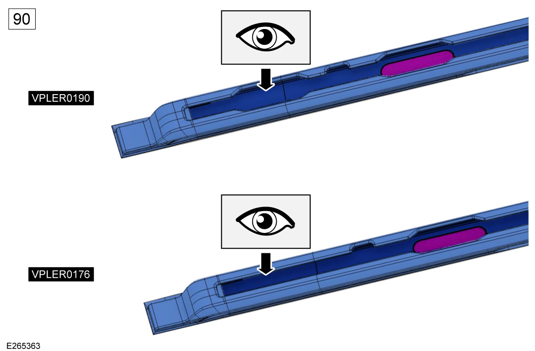
Inspect which type of roof rail you have by comparing with the roof rail illustration above. 'Roof Rails' (VPLER0190) has an additional slot at the rear of the roof rail and is the preferred roof rail if you not yet ordered one.

  • 'Roof Rails' (VPLER0190) are applicable with both 'Cross Bars' and 'Deployable Roof Ladder' installed at the same time. If you plan to install the 'Cross Bars' in conjunction with the 'Deployable Roof Ladder'. Then it is recommended you order 'Roof Rails' (VPLER0190).
  • 'Roof Rails' (VPLER0176) are 'NOT' applicable with both 'Cross Bars' and 'Deployable Roof Ladder' installed at the same time.
2
WARNING
  • The labels on the 'Cross Bars' must be read. The labels show the correct cross bar for the front and the rear of the vehicle and also the correct orientation of the cross bars.

The front cross bar will be inserted first. Identify the front (B) and the rear (C) cross bars. Use the labels under cross bars to assist identification.

  • Look for the arrow next to the graphic of the vehicle. The arrow will point at the front or rear cross bar on the vehicle graphic.
3

Unlock and remove all side covers from both front and rear cross bars.

  1. Using the supplied key (A), unlock the side covers.
  2. Move the side cover outwards.
  3. Squeeze in the x2 metal pins together to remove the side covers completely.
4
NOTE
  • Only complete this step when installing the cross bar to the vehicle for the first time.
  • The cross bars are different lengths. After the x2 cross bar finishers (D) have been cut to length they will only install to the cross bar they are installed into. If the cross bar finishers are removed, they must be replaced into the correct cross bar and do not cut again.

Install and cut the cross bar finishers (D) on both front and rear cross bars.

  1. Install the cross bar finishers (D) into the cross bars (B) and (C) by pushing down along the length of the finisher.
  2. Cut the x2 cross bar finishers to the required length.
5

Inspect both cross bars or correct orientation.

  • Inspect the orientation of the cross bars are correct in relation to the vehicle, as illustrated. The thicker part of the cross bar needs to be facing towards the rear of the vehicle with the cross bar labels located under the cross bars on the left side of the cross bars.
6
WARNING
  • This step requires the aid of another person.

Identify the x2 access slots on the top of the roof rails. Then offer up the front cross bar into position and slot into place.

7
WARNING
  • The 'Cross Bars' must be installed into the small cutouts (illustrated with a black arrow). If the 'Cross Bars' are not installed into the cutout there is a risk the 'Cross Bars' and any load supported on them is not secure.
NOTE
  • This step is for both sides of the vehicle (left side shown).

Slide front cross bar into position on both sides of the vehicle.

  1. Pull the bracket outwards.
  2. Slide the front cross bar towards the front of the vehicle while keeping the bracket pulled outwards, into the small cut out identified by the black arrow on the graphic. Then release bracket.
  3. The front cross bar must be in the correct position and does not move by trying to slide the cross bar back and forth.
8
WARNING
  • This step requires the aid of another person.
CAUTION
  • This step is 'ONLY' for vehicles without a 'Deployable Roof Ladder'. If your vehicle has the 'Deployable Roof Ladder' then skip to STEP 11.

Identify the x2 access slots on the top of the roof rails. Then offer up the cross bar into position and slot into place.

9
WARNING
  • The 'Cross Bars' must be installed into the small cutouts (illustrated with a black arrow). If the 'Cross Bars' are not installed into the cutout there is a risk the 'Cross Bars' and any load supported on them is not secure.
NOTE
  • This step is for both sides of the vehicle (left side shown).

Slide rear cross bar into position on both sides of the vehicle.

  1. Pull the bracket outwards.
  2. Slide the rear cross bar towards the rear of the vehicle while keeping the bracket pulled outwards, into the small cut out identified by the black arrow on the graphic. Then release bracket.
  3. The rear cross bar must be in the correct position and does not move by trying to slide the cross bar back and forth.
10

Inspect to make sure the cross bars are correctly installed on both sides of the vehicle. Then skip to STEP 16.

11
WARNING
  • This step requires the aid of another person.
NOTE
  • The following steps are only required for the installation of the rear cross bar to 'Roof Rails' (VPLER0190) if you have the 'Deployable Roof Ladder' installed.

Identify the access slot on the top of the roof rail for the right side of the rear cross bar. Then offer up the cross bar into position and slot into place.

12
NOTE
  • 'Exterior Side-Mounted Gear Carrier' shown in illustration but this step is applicable to vehicles with or without the 'Exterior Side-Mounted Gear Carrier'.

Slide the rear cross bar into position on right side of vehicle 'ONLY'.

  1. Pull the bracket outwards.
  2. Slide the rear cross bar while keeping the bracket pulled outwards towards the rear of the vehicle until it almost touches the 'Exterior Side-Mounted Gear Carrier' if one is installed. If no 'Exterior Side-Mounted Gear Carrier' is installed then a similar position is fine.
13

Identify the access slot on the top of the roof rail for the left side of the rear cross bar and slot into place.

14
WARNING
  • The 'Cross Bars' must be installed into the small cutouts (illustrated with a black arrow). If the 'Cross Bars' are not installed into the cutout there is a risk the 'Cross Bars' and any load supported on them is not secure.
NOTE
  • This step is for both sides of the vehicle (left side shown).

Slide rear cross bar into position on both sides of the vehicle.

  1. Pull the bracket outwards.
  2. Slide the rear cross bar towards the front of the vehicle while keeping the bracket pulled outwards, into the small cut out identified by the black arrow on the graphic. Then release bracket.
  3. The rear cross bar must be in the correct position and does not move by trying to slide the cross bar back and forth.
15

Inspect to make sure the cross bars are correctly installed on both sides of the vehicle.

16

Tighten the highlighted fixing with the torque key (E) on all ends of the cross bars.

  1. Loosely tighten the fixing on the left side of the cross bar.
  2. Fully Tighten the fixing on the right side of the cross bar until it clicks.
  3. Fully tighten the fixing on the left side of the cross bar until it clicks.
17
NOTE
  • The cross bar side covers are handed. The thicker part needs to be facing towards the rear of the vehicle.
  • Installation of side covers is the reversal of STEP 3.

Install and close the cross bar side covers on all ends of the cross bars and are correctly installed and then locked using key (A).

18
WARNING
  • Do not exceed 130 km/h or 80 mph when the 'Cross Bars' are installed.

Speed Limit.

© Land Rover 2016