LAND ROVER ACCESSORY FITTING INSTRUCTIONS

VEHICLE :
PART NO :
KEYWORD :

LAND ROVER

DEFENDER

DEPLOYABLE ROOF LADDER

VPLER0172 / VPLER0189 / VPLER0196

FITTING INSTRUCTION

WARNING
  • Accessories which are not correctly installed can be dangerous. Read the instructions carefully prior to ordering and installation to make sure this accessory is applicable to your variant of vehicle. Comply with instructions at all times. If in doubt, contact your nearest approved retailer.
Kits Required Part Number
Deployable Roof Ladder - Defender 90/110 VPLER0172 or VPLER0189 or VPLER0196
Deployable Roof Ladder - Defender 130 VPLER0196

Warnings / Cautions / Notes

WARNING
  • Take extra care when climbing on the deployable roof ladder in wet or icy conditions.
  • Take care when stowing or deploying the deployable roof ladder to make sure that fingers do not get trapped by the ladder. It is advisable to hold the middle step of the deployable roof ladder when latching the ladder shut or deploying the ladder.
  • The maximum load that can be placed on the deployable roof ladder is 150 kg or 330 lbs. Do not exceed the maximum load.
CAUTION
  • The vehicle must be equipped with roof rails if the deployable roof ladder is going to be installed.
  • If both the deployable roof ladder and the expedition roof rack will be installed to the vehicle then the expedition roof rack rear feet must be installed first and the deployable roof ladder installed afterwards.
  • Do not loosen any fixings already installed on the deployable side steps prior to installation.
  • Make sure the correct stowing sequence is followed to prevent damage to the deployable roof ladder.
NOTE
  • The deployable roof ladder can be installed to both right and left side of the vehicle, however the ladder must be installed to the left side 'ONLY' if the 'Exterior Side mounted Gear carrier' is also being installed.

Deployable Roof Ladder (Bill of Materials)

Bill Of Materials Replacement Service Part Number
(A) Deployable Roof Ladder N/A
(B) Roof Brackets - x2 N/A
(C) M6 Spacer - x2 N/A
(D) M10 Spacer - x2 N/A
(E) Sleeve - x2 N/A
(F) M6x16 Fixing - x2 N/A
(G) M10 Large Washer - x4 N/A
(H) M10x55 Fixing - x2 N/A
(J) Trim Cover LR175049 or LR166274
(K) Keys N/A
(L) M10 Small Washer - x2 N/A
(M) Metal Clip - x3 N/A
REMOVAL INSTRUCTIONS
1
CAUTION
  • The 'Deployable Roof Ladder' is not intended to be removed when installed.
NOTE
  • This step is 'ONLY' applicable for Defender 90.

Inspect which type of roof rail you have by comparing with the roof rail illustration above. 'Roof Rails' (VPLER0190) has an additional slot at the rear of the roof rail and is the roof rail of choice to order if you have not yet ordered one.

  • 'Roof Rails' (VPLER0190) are applicable with multiple roof accessories and 'Deployable Roof Ladder' installed at the same time. If you plan to install the other roof accessories in conjunction with the 'Deployable Roof Ladder'. Then it is recommended you order 'Roof Rails' (VPLER0190).
  • 'Roof Rails' (VPLER0176) are 'NOT' applicable with both 'Cross Bars' and 'Deployable Roof Ladder' installed at the same time.
2
NOTE
  • Make sure all trim clips are removed from the body and are undamaged.

Identify the left side trim as illustrated.

3

Clean the surface of the side trim as illustrated.

4

Mask the vehicle body and the glass above and below the side trim.

5

Use suitable tooling to remove the side trim.

6
NOTE
  • Complete step 'ONLY' for Defender 110/130.

Remove the protection sealing patches that are located over the vehicle body fixing nuts as illustrated.

  • The right side of the vehicle has x3 vehicle body fixing nuts in this section of the vehicle body. Make sure only the x2 furthest forward nuts are exposed.
7
NOTE
  • Complete step 'ONLY' for Defender 90.

Remove the protection sealing patches that are located over the vehicle body fixing nuts as illustrated.

  • The right side of the vehicle has x3 vehicle body fixing nuts in this section of the vehicle body. Make sure only the x2 furthest forward nuts are exposed.
8

Mark guide lines on the masking tape showing the center of the vehicle body fixing nuts as illustrated.

9

Measure from the bodyside feature to the center of the vehicle body fixing nuts and record the measurements.

10
CAUTION
  • Make sure the clips are securely located in the body holes.
  • Make sure the seal is lipped under the glass.

Install the side trim to the vehicle as illustrated.

11
NOTE
  • Take care to mark the hole positions accurately.

Mark the side trim with the location of the x2 holes that need to be drilled. Use the guide lines produced in step 8 and the measurements step 9 to define the hole positions.

12
NOTE
  • Make sure all clips are removed from the body and are undamaged.

Use suitable tooling to remove the side trim.

Fitting Instruction
1
WARNING
  • Make sure to wear suitable personal protective equipment.
NOTE
  • Complete step 'ONLY' for Defender 110 and 130.

Use appropriate tooling to cut away the x2 arrowed metal strips (this will make drilling easier in the step 3).

  • Removing the metal strips will make drilling easier.
2
WARNING
  • Make sure to wear suitable personal protective equipment.
NOTE
  • Complete step 'ONLY' for Defender 90.

Use appropriate tooling to cut away the x2 arrowed metal strips (this will make drilling easier in the step 4).

  • Removing the metal strips will make drilling easier.
3
WARNING
  • Make sure to wear suitable personal protective equipment.
NOTE
  • Complete step 'ONLY' for Defender 110 and 130.

Vehicles with 110 and 130 wheelbase only. Drill x2 holes in the removed side trim as illustrated.

  1. Drill a pilot hole at the x2 marked locations.
  2. Drill holes at the x2 locations. Use a 20mm step drill bit.
4
WARNING
  • Make sure to wear suitable personal protective equipment.
NOTE
  • Complete step 'ONLY' for Defender 90.

Vehicles with 90 wheelbase only. Drill x2 holes in the removed side trim as illustrated.

  1. Drill a pilot hole at the x2 marked locations.
  2. Drill holes at the x2 locations. Use a 19mm drill bit.
5
CAUTION
  • Make sure the clips are securely located in the body holes.
  • Make sure the seal is lipped under the glass.

Install the side trim to the vehicle as illustrated.

6

Remove the masking tape from the side of the vehicle.

7
CAUTION
  • Make sure the brackets are installed in the correct orientation.
NOTE
  • If both the 'Deployable Roof Ladder' and the 'Expedition Roof Rack' will be installed to the vehicle then the 'Expedition Roof Rack' rear feet must be installed first and the 'Deployable Roof Ladder' installed afterwards.

Install x2 brackets (B) into the roof rail as illustrated. Make sure the orientation of the brackets is correct. The arrowed surface of the bracket is larger and must face towards the center of the vehicle.

  1. Insert the brackets into the roof rail as illustrated. The roof rail has wider apertures that allow the brackets to be installed into the roof rail.
  2. Slide the brackets to the approximate correct position so they align with the holes in the side trim.
8
NOTE
  • This step requires the aid of another person.
  • Make sure the ladder does not damage the vehicle trim. Install some protection to the ladder to make sure there is a gap between the ladder and the vehicle trim.

Install the top part of the deployable roof ladder to the vehicle and the x2 brackets (B).

  1. Align the fixing holes at the top of the deployable roof ladder with the x2 brackets (B) in the roof rails.
  2. Install, but do not fully tighten fixings (F). The fixings will pass through the spacer (C), the fixing holes in the deployable roof ladder and then into the bracket (B).
9
WARNING
  • Take care when deploying the deployable roof ladder to make sure that fingers do not get trapped by the ladder. It is advisable to hold the middle rung of the deployable roof ladder when deploying the ladder.
CAUTION
  • For Defender 110, make sure the edge of the ladder does not overlap the rubber seal along the edge of the second row door. There must be a gap between the ladder and the rubber seal.
NOTE
  • This step requires the aid of another person.

Align the 2 fixing holes in the middle section of the deployable roof ladder with the x2 holes in the side trim.

  1. Hold the arrowed middle step of the deployable roof ladder and pull the release handle.
  2. Pull down the deployable roof ladder to the illustrated position.
  3. Move the deployable roof ladder along the roof rail, as required, so the x2 fixing holes in the middle section of the ladder align with the x2 holes in the side trim.
  4. For Defender 110/130, make sure the arrowed edge of the ladder does not overlap the rubber seal along the edge of the second row door. There must be a gap between the ladder and the rubber seal. Adjust if required.
  5. Make sure the x2 holes in the side trim are visible through the ladder.
  6. For Defender 110/130, carefully open and close the second row door to make sure the edge of the ladder does not interfere with the rubber seal along the edge of the second row door.
10
NOTE
  • Make sure there is a consistent gap between the deployable roof ladder and the vehicle body.
  • Install but do not fully tighten fixings.

Secure the middle part of the deployable roof ladder to the vehicle body.

  1. Install the x2 sleeves (E) into the holes in the side trim.
  2. Install fixing (H) that will pass through washer (G) and spacer (D). Then through the fixing holes in the middle of the deployable roof ladder to washers (G) and (L) to the back of the ladder and then into the sleeve (E) in the side trim.
11
NOTE
  • Centralising the slots will make sure there is no clash between clips and rail when fitting the top cap.
  • Use the slots arrowed as a guide to centralise the fixings.

Centralise the fixings in the middle of the fixing holes. Prioritise the holes indicated for the wheelbase version of your vehicle.

12

Incorrect positioning shown.

13

Fully tighten the x2 fixings (F) at the top of the deployable roof ladder.

  • Torque: 6Nm
14

Fully tighten the x2 fixings (H) at the middle of the deployable roof ladder.

  • Torque: 48Nm
15

Remove the protection from around the ladder.

16
WARNING
  • Take care when stowing or deploying the deployable roof ladder to make sure that fingers do not get trapped by the ladder. It is advisable to hold the arrowed middle rung of the deployable roof ladder when latching the ladder shut or deploying the ladder.

Move the deployable roof ladder to the stowed position.

17
NOTE
  • This step is 'ONLY' for Defender 90/110 vehicles with old ladder part numbers (VPLER0172 or VPLER0189) with new trim cover (J) part number (LR175049).

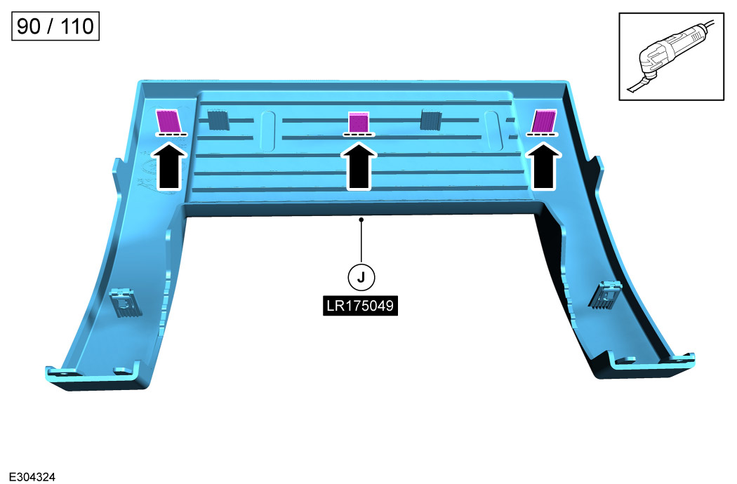
When it is time to install the trim cover (J) please inspect which deployable roof ladder you have installed (VPLER0172 / VPLER0189 or VPLER0196).

  • If trim cover (J) LR175049 has been ordered you will need to cut x3 tabs as illustrated for Defender 90/110 with deployable roof ladder (VPLER0172 or VPLER0189).
  • If trim cover (J) LR166274 has been ordered no cutting is necessary, as that will install to all deployable roof ladder variants.
18
NOTE
  • Complete step 'ONLY' for Defender 130.

Match the correct clip and slot combination to the wheelbase of your vehicle.

19
NOTE
  • Complete step 'ONLY' for Defender 90/110.

Match the correct clip and slot combination to the wheelbase of your vehicle.

20

Install the metal clips (M) on the plastic pins for the correct wheelbase of your vehicle.

21
NOTE
  • Make sure all top cap clips are fully engaged into the ladder.

Install the trim cover (J) to the deployable roof ladder as illustrated.

22
WARNING
  • Take care when stowing or deploying the deployable roof ladder to make sure that fingers do not get trapped by the ladder. It is advisable to hold the arrowed middle rung of the deployable roof ladder when latching the ladder shut or deploying the ladder.

Follow steps 22 and 23 for instructions on how to deploy the deployable roof ladder.

23
WARNING
  • Take care when stowing or deploying the deployable roof ladder to make sure that fingers do not get trapped by the ladder. It is advisable to hold the arrowed middle rung of the deployable roof ladder when latching the ladder shut or deploying the ladder.

Open the deployable roof ladder to the first position as illustrated.

  1. Hold the arrowed middle step of the deployable roof ladder.
  2. Pull the release handle.
  3. Pull the deployable roof ladder down and outwards until the arrowed brackets lock and the ladder will not move further.
24
WARNING
  • Take care when stowing or deploying the deployable roof ladder to make sure that fingers do not get trapped by the ladder.
CAUTION
  • Make sure the correct stowing sequence is followed to prevent damage to the deployable roof ladder.

Extend the deployable roof ladder to the full length as illustrated.

  1. Hold the arrowed top step and pull the deployable roof ladder outwards.
  2. Extend the deployable roof ladder to the full length.
25
WARNING
  • Take care when stowing or deploying the deployable roof ladder to make sure that fingers do not get trapped by the ladder.
CAUTION
  • Make sure the correct stowing sequence is followed to prevent damage to the deployable roof ladder.

When not in use make sure the deployable roof ladder is installed securely and is locked in the stowed position.

  • Follow steps 25 and 26 to stow the deployable roof ladder correctly.
26
WARNING
  • Take care when stowing or deploying the deployable roof ladder to make sure that fingers do not get trapped by the ladder.
CAUTION
  • Make sure the correct stowing sequence is followed to prevent damage to the deployable roof ladder.

Stow the deployable roof ladder.

  1. Hold the lowest step of the deployable roof ladder and fold the ladder upwards.
  2. Make sure the deployable roof is positioned as illustrated.
27
WARNING
  • Take care when stowing or deploying the deployable roof ladder to make sure that fingers do not get trapped by the ladder. It is advisable to hold the middle rung of the deployable roof ladder when latching the ladder shut or deploying the ladder.
  • Make sure that the deployable roof ladder is securely latched and locked before driving the vehicle.
CAUTION
  • Make sure the correct stowing sequence is followed to prevent damage to the deployable roof ladder.

Stow the deployable roof ladder.

  1. Hold the arrowed middle step of the deployable roof ladder.
  2. Push the deployable roof ladder up and inwards. The arrowed brackets will release allowing the ladder to move.
  3. An audible click is heard when the deployable roof ladder is correctly stowed as illustrated.
  4. Use the supplied key (K) to lock the deployable roof ladder.
© Land Rover 2016