LAND ROVER ACCESSORY FITTING INSTRUCTIONS

VEHICLE :
PART NO :
KEYWORD :

LAND ROVER

DEFENDER

'A' FRAME PROTECTION BAR

VPLEP0385 / VPLEB0437 / VPLEB0435 / VPLEB0436 / VPLEB0434 / VPLEB0441 / LR137889

FITTING INSTRUCTION

WARNING
  • Accessories which are not correctly installed can be dangerous. Read the instructions carefully prior to installation. Comply with instructions at all times. If in doubt, contact your nearest approved retailer.
Accessory Part Number
'A' Frame Protection Bar VPLEP0385
Defender-X 'ONLY' Front Bumper Protector VPLEB0441
Camera Mounting Kit (Optional) VPLEB0437
Parking Aid Sensors (Optional) LR137889
China Market Number Plate Plinth VPLEB0434
EU Market Number Plate Plinth VPLEB0435
NAS / Japan Market Number Plate Plinth VPLEB0436
CAUTION
  • For Defender-X vehicles 'ONLY', the prepared 'Front Bumper Protector' - VPLEB0441 must be ordered.
REMOVAL INSTRUCTIONS
1

Open the hood.

2

Remove the hood latch panel finisher.

  • Remove the x6 clips.
  • Remove the hood latch panel finisher.
3
NOTE
  • This step requires the aid of another technician.
  • Make sure all fixings are retained.

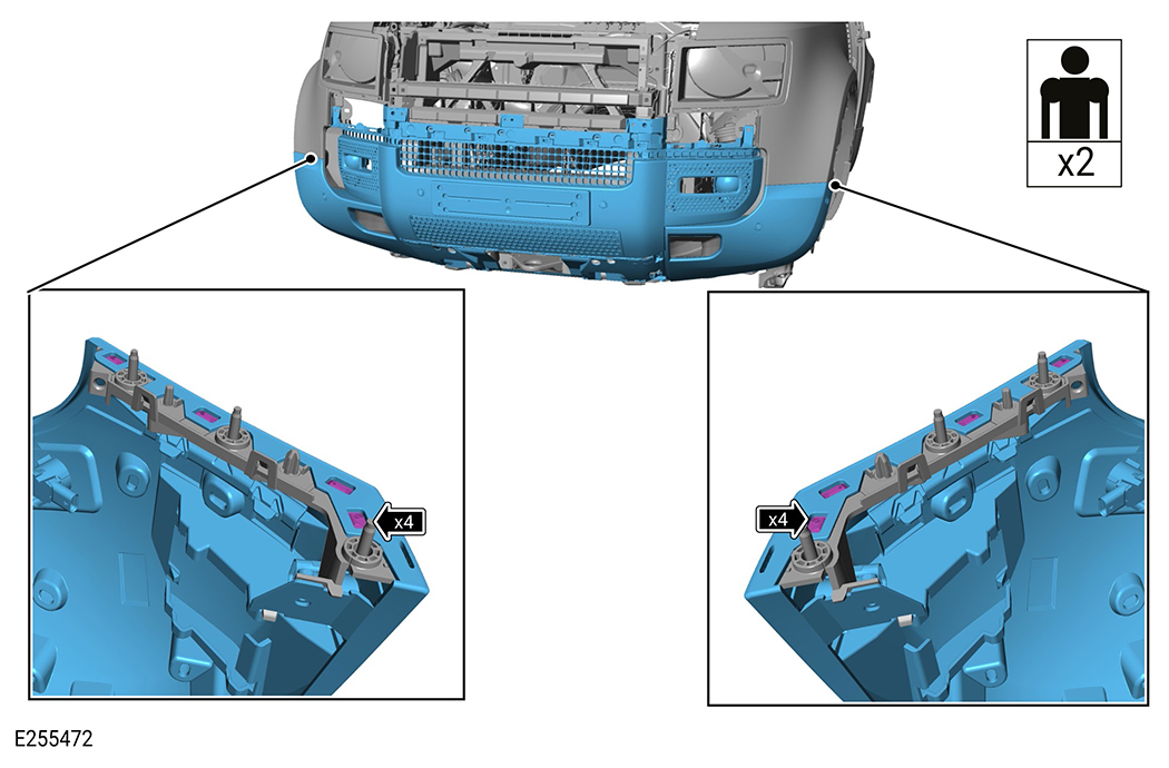
Remove the front bumper from the vehicle. Complete only steps 1 to 15 of the referenced front bumper workshop manual. For additional information, please refer to the official Workshop Manual. Front Bumper (501-19 Bumpers) Then continue following the accessory procedure.

4
NOTE
  • The x2 removed parking aid sensors will be replaced with 2 black parking aid sensors (LR137889) that get installed to the A-frame cover.

Remove and discard the x2 parking aid sensors from the front bumper.

  1. Disconnect the parking aid sensor harness from the parking aid sensor.
  2. Remove the parking aid sensor from the front bumper.
5
CAUTION
  • This step must be completed to make sure there is sufficient harness length to allow the camera to be installed to the A-frame cover.

Remove the arrowed tape and the arrowed clip securing the camera harness to the front wiring harness.

6

Disconnect the camera harness from the camera.

7
NOTE
  • Retain the license plate and the license plate fixings.

Remove the license plate and the license plate fixings.

8
NOTE
  • The existing vehicle license plate plinth cannot be installed to the 'A' frame protection bar. A new license plate plinth must be ordered that can be installed to the 'A' frame protection bar. The correct license plate plinth for the vehicle market must be ordered.

Remove the license plate plinth if installed. Discard the license plate plinth.

9
CAUTION
  • Take extra care not to damage the clips.
NOTE
  • Repeat this step for the other side.

Remove the fog lamp finisher.

  • Release x7 clips.
  • Remove the fog lamp finisher from front bumper.
10

Remove x6 fixings.

11
CAUTION
  • Take extra care not to damage the clips.
NOTE
  • Make sure all fixings are retained.

Remove the front bumper protector.

  • Remove x2 fixings.
  • Release x20 clips.
12

Remove the camera housing and the front proximity camera from the front bumper grille part.

  • Remove (x3) fixings.
13

Remove the front proximity camera from the camera housing.

  1. Remove the front proximity camera from the camera housing. Retain the front proximity camera (S2).
  2. Discard the camera housing.
14
CAUTION
  • For Defender-X vehicles 'ONLY', the prepared front bumper protector (VPLEB0441) must be ordered. The front bumper protector comes already pre-cut.
NOTE
  • Make sure to remove and retain the grille part of the front bumper protector removed from the vehicle.

For Defender-X vehicles 'ONLY', do not complete steps 15 to 20. Continue from step 21.

  • Install the front grille taken from the removed front bumper protector, and install it to the Defender-X front bumper protector (VPLEB0441).
  • Do not discard the old front bumper protector that was removed from the vehicle although the front bumper protector (VPLEB0441) will be installed instead.
15
NOTE
  • Take care to mark the hole position accurately.

Mark a point at the centre of the front bumper protector.

  • Make sure the mark is centred between the x2 parking aid sensor holes.
16
WARNING
  • Make sure to wear suitable personal protective equipment.

Drill a hole at the marked position.

  • 22 mm drill bit
17
CAUTION
  • There are multiple cut guide lines on the front bumper protector. There is a risk of irreversible damage to the part if the correct cut guide lines are not followed.
NOTE
  • The cut guide lines are found on the reverse side of the part.

Identify the correct cut guide lines on the front bumper protector.

18
WARNING
  • Make sure to wear suitable personal protective equipment.
CAUTION
  • There are multiple cut guide lines on the surface of the part. Make sure the correct cut guide lines are followed as illustrated.

Use suitable tooling to cut the illustrated sections from the front bumper protector. Discard the removed sections.

  • Use the cut guide lines on the front bumper protector.
19
CAUTION
  • There are multiple cut guide lines on the front bumper protector. There is a risk of irreversible damage to the part if the correct cut guide lines are not followed.
NOTE
  • The cut guide lines are found on the reverse side of the part.

Identify the correct cut guide lines on the front bumper protector for the parking aid sensor holes.

20
WARNING
  • Make sure to wear suitable personal protective equipment.
CAUTION
  • There are multiple cut guide lines on the surface of the part. Make sure the correct cut guide lines are followed as illustrated.

Use suitable tooling to drill the illustrated parking aid sensor holes in the front bumper protector. Discard the removed sections.

  • Use the cut guide lines on the front bumper protector.
  • The holes can be drilled using a 32 mm to 40 mm circular saw.
21
CAUTION
  • Extra care must be taken to avoid cutting the arrowed feature.
NOTE
  • The cut guide lines are found on the reverse side of the part.

Identify the correct cut guide lines on the radiator grille.

22
WARNING
  • Make sure to wear suitable personal protective equipment.
CAUTION
  • There are multiple cut guide lines on the surface of the part. Make sure the correct cut guide lines are followed as illustrated.

Use suitable tooling to cut the illustrated sections from the radiator grille. Discard the removed sections.

  • Use the cut guide lines on the radiator grille.
Fitting Instruction
1
NOTE
  • Install, but do not fully tighten the x4 fixings (D).

Install the x2 lower brackets (L) to the front bumper carrier using x4 fixings (D), the x8 washers (S) and the x4 nuts (T).

2

Position the A-frame carrier (A) onto the front bumper carrier and make sure the 2 brackets (L) are positioned correctly.

  1. Make sure the 4 arrowed cutouts in the A-frame carrier (A) are positioned correctly over the brackets (L) on both sides of the front bumper carrier.
  2. If required adjust the position of the brackets (L).
3

Remove the A-frame carrier (A) from the front bumper carrier.

4

Tighten the x4 fixings (D) that secure the x2 lower brackets (L) to the front bumper carrier.

  • Torque: 12Nm
5

Feed the camera harness through the illustrated hole in the grille part of the front bumper carrier. This is the hole to the side of the hole previously used by the camera.

  • The camera harness must be accessible from the front of the bumper carrier.
6
CAUTION
  • Care must be taken to avoid damaging the surrounding paintwork.
  • Take care not to damage the camera wiring harness and the parking aid sensor harnesses during the install of the front bumper carrier.
NOTE
  • Do not install the fully assembled front bumper to the vehicle at this stage.
  • This step requires the aid of another technician.

Install the front bumper carrier to the front of the vehicle.

  • Install x8 front bumper clips on both sides.
  • Install x6 lower clips to the front bumper.
  • Install and tighten the upper x5 fixings to the front bumper. Torque: 3.2Nm
7
NOTE
  • Repeat this step for the other side.

Install the front bumper finisher.

  • Install x7 clips.
8
NOTE
  • Install, but do not fully tighten (x4) fixings (D).

Install the x2 upper brackets (E) to the front of the vehicle using the x4 fixings (D), the x8 washers (S) and the x4 nuts (T).

9

Position the A-frame carrier (A) against the front bumper and make sure the x2 brackets (E) are positioned correctly.

  1. Make sure the arrowed cutouts in the A-frame carrier (A) are positioned correctly over the brackets (E) on both sides of the vehicle.
  2. If required adjust the position of the brackets (E).
10

Remove the A-frame carrier (A) from the front bumper.

11

Tighten the x4 fixings (D) that secure the x2 upper brackets (E) to the front bumper.

  • Torque: 12Nm
12

If required install the upper grille to the radiator grille.

  • Install x10 clips.
  • Install the upper grille.
13

Install the radiator grille. Take care when installing the radiator grille over the 2 upper brackets (E).

  • Install x14 clips.
  • Install the radiator grille.
  • Install x4 clips.
14
CAUTION
  • For Defender-X only vehicles the prepared front bumper protector (VPLEB0441) must be installed.
NOTE
  • The 2 lower brackets (L) will be located in the 2 cutouts in the front bumper protector.
  • Make sure the parking aid sensor harnesses are fed through the outer hole on each side of the front bumper protector.

Install the front bumper protector to the front bumper.

  1. Feed the x2 centre parking aid sensor harnesses through the illustrated holes in the front bumper protector.
  2. Install the x20 front bumper protector clips.
  3. Install and tighten the x8 fixings. Torque: 4Nm
15
CAUTION
  • Take extra care not to damage the clips.
NOTE
  • Repeat this step for the other side.

Install the fog lamp finisher to the front bumper.

  • Install x7 clips.
16
NOTE
  • This step requires the aid of another technician.
  • Install but do not fully tighten the (x8) fixings (D).

Install the A-frame carrier (A) using the x8 bolts (D) and the washers (S) to check the alignment.

  1. Make sure the A-frame carrier location pin is aligned with the hole in the centre of the front bumper protector.
  2. Align the A-frame carrier to the x4 brackets (E) and (L).
17

Make sure the gap between the arrowed edges on the A-frame carrier (A) and the arrowed edges on the front bumper are equal on both sides of the vehicle.

18

Remove the A-frame carrier (A) from the vehicle.

19

Install the front bumper lower cover.

20

Install x10 fixings (G) to the A-frame carrier (A).

21

Install the x14 rib locks (K) to the A-frame carrier (A).

22

Install x6 clips (H) to the A-frame carrier (A).

23
NOTE
  • This step requires the aid of another technician.

Position the A-frame carrier (A) close to the front bumper so the location pin on the A-frame carrier is aligned with the hole drilled in the centre of the front bumper bracket.

  1. Feed the harness for the parking aid sensors through the arrowed holes in the A-frame carrier (A) on both sides of the vehicle.
24
NOTE
  • This step requires the aid of another technician.
  • Install, but do not fully tighten the (x8) fixings (D).

Install the A-frame carrier (A) using x8 fixings (D) and the washers (S).

  1. Make sure the A-frame carrier location pin is aligned with the hole in the centre of the front bumper bracket.
  2. Align the A-frame carrier to the x4 brackets (E) and (L).
25

Make sure the gap between the arrowed edges on the A-frame carrier (A) and the arrowed edges on the front bumper are equal on both sides of the vehicle.

26

Tighten (x8) Fixings (D).

  • Torque: 12Nm
27
NOTE
  • Complete step only if required.
  • If required order the license plate plinth depending on the vehicle market.

Prepare the A-frame cover (B) so the correct license plate plinth can be installed if required.

  • Mark the location where the 2 holes should be drilled.
28
NOTE
  • Complete step only if installing a China market license plate plinth (VPLEB0434).
  • The markings for the holes are located on the inside of the A-frame cover (B).
  • Do not install the license plate plinth at this stage.

Drill 2 holes into the A-frame cover (B) at the illustrated positions. Arrowed locations are for China market license plate plinth.

  • 2 mm drill bit
29
NOTE
  • Complete step only if installing a NAS or Japan market license plate plinth (VPLEB0436).
  • The markings for the holes are located on the inside of the A-frame cover (B).
  • Do not install the license plate plinth at this stage.

Drill 2 holes into the A-frame cover (B) at the illustrated positions. Arrowed locations are for NAS or Japan market license plate plinth.

  • 2 mm drill bit
30
NOTE
  • Complete step only if installing a EU market license plate plinth.
  • The markings for the holes are located on the inside of the A-frame cover (B).
  • Do not install the license plate plinth at this stage.

Drill 2 holes into the A-frame cover (B) at the illustrated positions. Arrowed locations are for EU market license plate plinth (VPLEB0435).

  • 2 mm drill bit
31

Install x2 black parking aid sensors (U) to the parking aid sensor brackets that are part of the A-frame cover (B).

32

Position the A-frame cover (B) close to the A-frame carrier (A).

33
NOTE
  • This step requires the aid of another technician.
  • The A-Frame Cover (B) must be positioned close to the A-frame carrier (A) to connect the parking aid sensor harnesses.

Connect the parking aid sensor harnesses to the parking aid sensors in the A-frame cover (B).

  1. Make sure the parking aid sensor harness is accessible through the A-frame carrier (A).
  2. Connect the parking aid sensor harness to the parking aid sensor on the A-frame cover (B).
34

Make sure x2 black parking aid sensors (U) are installed correctly and the parking aid sensor harness is connected as illustrated.

35
CAUTION
  • Take care to avoid damage to the parking aid sensor harnesses as the A-frame cover is installed.

Install the A-frame cover (B) to the A-frame carrier (A).

  1. Apply force at all positions where clips are located.
  2. Make sure all clips are fully engaged.
  3. Check the alignment of the A-frame cover (B).
36

Install x10 fixings (F) to secure the A-frame cover (B) to the A-frame carrier (A). The fixings (F) will pass through the clips (G).

  • Torque: 8 Nm
37

Install x7 remaining rib locks (K) to the A-frame centre trim (C).

38
NOTE
  • If the front proximity camera will be installed then the 'Camera Mounting Kit' VPLEB0437 must be used.

Install the camera bracket (J) to the A-frame centre trim (C).

  1. Align and locate the camera bracket (J) to the A-frame centre trim (C).
  2. Make sure the camera bracket is correctly installed as illustrated.
  3. Install x2 fixings (I).
39

Install the A-frame centre trim (C) to the A-frame cover (B).

  1. Install the A-frame centre trim top clips first and then push in the bottom clips.
40
CAUTION
  • Take care when handling the camera. Avoid touching the camera lens.

Connect the front proximity camera (S2) to the camera harness.

  • The camera harness will already have been fed through the grille part of the front bumper.
41
CAUTION
  • Take care when handling the camera. Avoid touching the camera lens.

Install the camera housing (T) to the A-frame centre trim (C).

  1. Carefully install the front proximity camera (S2) into the camera housing (T).
  2. Install the camera housing (T) to the camera bracket (J). Make sure the camera housing is correctly engaged into the bracket (J).
  3. Secure the camera housing to the camera bracket using the screw (I).
42
CAUTION
  • If the front proximity camera is installed then take care not to damage the camera as the plinth is being installed.
  • Make sure the license plate plinth is installed correctly and is not distorted.
NOTE
  • Complete step only if required.

Install the license plate plinth to the A-frame cover (B) using x2 fixings (N) and the 2 holes drilled in install steps 24 to 27.

  1. China market - VPLEB0434.
  2. NAS / Japan market - VPLEB0436.
  3. EU market - VPLEB0435.
43
NOTE
  • Complete step only if required.

Install the remaining x6 fixings (N) to the license plate plinth.

  1. China market.
  2. NAS or Japan market.
  3. EU market.
44

Install the license plate to the license plate plinth.

45


  • Install the hood latch panel finisher.
  • Install x6 clips.
© Land Rover 2016