LAND ROVER ACCESSORY FITTING INSTRUCTIONS

VEHICLE :
PART NO :
KEYWORD :

LAND ROVER

DISCOVERY

DASH CAM

T4C1010 / VPLKV0134

FITTING INSTRUCTION

WARNING
  • Accessories which are not correctly installed can be dangerous. Read the instructions carefully prior to ordering and installation to make sure this accessory is applicable to your variant of vehicle. Comply with instructions at all times. If in doubt, contact your nearest approved retailer.
NOTE
  • Observe all state and local laws when using the Jaguar, Land Rover Accessory Dash Cam. Residents of AZ, CA, HI, I N, MD, MN, NV, OH, UT, and District of Columbia, consult windshield mounting restrictions before installing. Not for use in AL, AR, DE, GA, ID, IA, KS, KY, LA, MT, NE, NJ, NM, ND, OK, OR, PA, RI, SC, TX, VA, WA, WV, WI, WY. Since regulations are constantly changing, consult with your local authority or department of motor vehicle prior to use and operation.
Kits Part Number
Land Rover Dash Cam VPLKV0134
Jaguar Dash Cam T4C1010
Service Kit A 704123458
Service Kit B 704123456
Service Kit C 704123457

Dash Cam (Bill of Materials)

NOTE
  • SRO code for installation of the whole kit is 06.30.45
  • SRO code for just the front camera is 06.30.51
  • SRO code for just the rear view camera is 06.30.52

Service Kit A

NOTE
  • SRO code for just installation of the harness is 06.30.53
Vehicle platform SRO code and time
Jaguar XE 06.30.53 / 0.8 hours
Jaguar XJ 06.30.53 / 0.6 hours
New Defender / 90 / 110 / 130 06.30.53 / 1.8 hours
New Defender Commercial 06.30.53 / 2.0 hours
Range Rover Velar 06.30.53 / 1.8 hours
Range Rover Evoque 06.30.53 / 1.5 hours
All New-Discovery / Discovery Commercial 06.30.53 / 1.4 hours
Range Rover Sport 06.30.53 / 1.9 hours
Jaguar XF 06.30.53 / 1.0 hours
Jaguar XF Sportbrake 06.30.53 / 1.6 hours
Jaguar F-Pace 06.30.53 / 1.7 hours
New Range Rover Sport 06.30.53 / 1.9 hours
Range Rover SWB / LWB 06.30.53 / 2.0 hours
Discovery Sport 06.30.53 / 1.0 hours
Jaguar E-Pace 06.30.53 / 1.4 hours
New Range Rover SWB / LWB 06.30.53 / 1.8 hours

Service Kit B

NOTE
  • SRO code for installation of the bracket and adhesive pads is 06.30.55

Service Kit C

NOTE
  • SRO code for just installation of the SD Card is 06.30.54

Position of front camera.

NOTE
  • The position of the front camera depends on your vehicle specification.

Overview of harness routing.

Windshield temperature

CAUTION
  • Make sure the vehicle and parts being installed are at the correct temperature. In hot climate countries the windshield temperatures could be greater than 43°C if the vehicle is left in the sun. Move the vehicle into the workshop and allow 2 hours to reach workshop temperatures before installing the accessories. Use infa-red thermometer JLR-60051001 to inspect the vehicle windshield temperature is in the correct temperature range before installing the accessory.
  • If windshield is below the minimum temperature stated, turn on demister before application of adhesive tape, for intervals of 5-10 minutes, and assess the condition of the windshield making sure it is at the correct application temperature with use of the infa-red thermometer. This could also be used to remove any condensation and moisture.
  • Avoid excessively heating the windshield.
NOTE
  • Make sure proper ventilation in the car to prevent excessive humidity. Opening a window slightly can help release moisture from the car.
Fitting Instruction
NOTE
  • This procedure contains some variation in the illustrations depending on the vehicle specification, but the essential information is always correct.
1

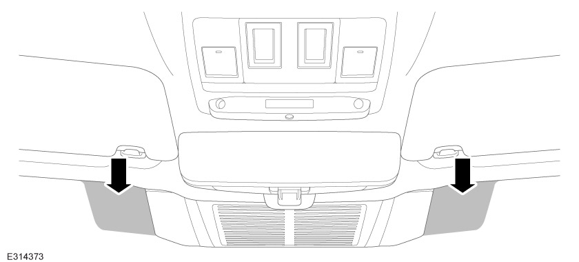
Remove the overhead console (Refer to the workshop manual) if required.

2
CAUTION
  • Make sure harness is not trapped.
NOTE
  • If harness is damaged order service kit A.
  • Remove sun visors if necessary for easier access.

Feed harness end (A4) through front headliner towards the right A-Pillar as illustrated. Use suitable tape and foam rolls (F) as required to prevent harness from rattling in the headliner.

3
NOTE
  • Pull harness to check if pins are not backed out.

Connect the Dash Cam connector (A2) to the dome lamp connector removed from the overhead console. An audible click will be heard when connected correctly.

4
CAUTION
  • Make sure the Dash Cam harness is secured to the vehicle harness using cable ties (G) where necessary.

Connect the Dash Cam connector (A3) to the vehicle dome lamp socket on the overhead console. And reinstall overhead console.

5
NOTE
  • Make sure the bracket is clear of any contaminants before applying double-sided adhesive pad.
  • If bracket or adhesive pad needs to be replaced order service kit B.

Peel off the white side of the double-sided adhesive pad (B2) and stick it to the bracket (A5).

6

Turn the bracket (A5) over and install (A1) to bracket by sliding it into place.

7
CAUTION
  • Temporarily secure dash cam to windshield using masking tape.

Install (A1) with bracket to front camera (B). An audible click will be heard when installed correctly.

8
CAUTION
  • 'DO NOT' interrupt the power supply.
  • 'DO NOT' remove the Dash Cam from the cradle.
  • 'DO NOT' remove the SD Card while the update is proceeding.

When first connected to a power supply, the Dash Cam 'MAY' automatically complete a firmware update when it is first connected to a power supply.

  1. If the firmware update process has started, this will be indicated by 3 beeps for each stage of the update. There are 2 update stages that need to take place for the firmware to be fully updated.
  2. During firmware update, amber lights on both buttons (1 and 2 in the image above) will start flashing.
  3. The update is finished when the amber Light Emitting Diode (LED) ’s on both buttons stop flashing and the green light comes on one button. The Dash Cam will also give an audible message through the unit to state “Recording Started”.
9
WARNING
  • Make sure cable routing does not obstruct airbag deployment.

Remove A-pillar trim and feed harness end (A4) down the A-pillar, securing to the vehicle harness with cable ties (G).

10
CAUTION
  • Make sure harness is not trapped when installing the trim.

Remove lower A-pillar and B-Pillar trim and front treadplate and feed harness end (A4) through to the lower B-pillar securing to the vehicle harness where possible.

11
CAUTION
  • Make sure harness is not trapped when installing the trim.

Remove lower and upper C-pillar trim and upper D-pillar trim. Feed harness end (A4) up the C-Pillar into the headliner securing to the vehicle harness with cable ties (G). Use suitable tape and foam rolls (F) as required to secure harness to headliner and to prevent rattling.

12

For the correct tailgate routing procedure refer to the table below and go to the corresponding step.

Vehicle platform Illustration
Jaguar XE / XF / XJ Saloon (Step 13)
New Defender / 90 / 110 / 130 / Commercial Defender (Step 14)
Range Rover Velar Illustration A (Step 15)
Range Rover Evoque Illustration A (Step 15)
All New-Discovery / Discovery Commercial Illustration A (Step 15)
Range Rover Sport Illustration A (Step 15)
Jaguar XF Sportbrake Illustration A (Step 15)
Jaguar F-Pace Illustration A (Step 15)
New Range Rover Sport Illustration A (Step 15)
Range Rover SWB / LWB Illustration B (Step 16)
Discovery Sport Illustration C (Step 17)
Jaguar E-Pace Illustration C (Step 17)
New Range Rover SWB / LWB Illustration D (Step 18)
13
CAUTION
  • Do not stick rear view camera to the screen at this point.
NOTE
  • For vehicles installed with a rear window blind refer to image 'B' for rear view camera location.

Connect and position rear view camera (C).

  1. Feed harness (A) through the D-pillar and into the headliner and feed harness end (A4) out of the headliner as illustrated.
  2. Connect (A4) to rear view camera (C). Make sure the connection is fully seated in the camera socket.
  3. Temporarily secure rear dash cam to rear window using masking tape.
  4. At this point download and install the Dash Cam application. For additional information, please refer to the official Workshop Manual. Dash Cam - User Guide (102-02) and make sure both front and rear view cameras are working before proceeding to next step.
  5. With your rear view camera active on your application find a suitable location for the rear view camera, based roughly on the position shown in the illustration. Make sure the Dash Cam lens is 'NOT' obscured by rear screen heater elements. When you are happy with the position you want the rear view camera to be located proceed to step 19.
14
CAUTION
  • Do not stick the rear view camera to the screen at this point.

Connect and position rear view camera (C).

  1. Remove the inner tailgate trim (Refer to the workshop manual) if required. Feed Dash Cam harness through the tailgate as illustrated.
  2. Secure harness with glass routing clips (D).
  3. Connect (A4) to rear view camera (C). Make sure the connection is fully seated in the camera socket.
  4. Temporarily secure rear dash cam to rear window using masking tape.
  5. Install inner tailgate trim.
  6. At this point download and install the Dash Cam application. For additional information, please refer to the official Workshop Manual. Dash Cam - User Guide (102-02) and make sure both front and rear view cameras are working before proceeding to next step.
  7. With your rear view camera active on your application find a suitable location for the rear view camera, based roughly on the position shown in the illustration. Make sure the Dash Cam lens is 'NOT' obscured by rear screen heater elements. When you are happy with the position you want the rear view camera to be located proceed to step 19.
15
CAUTION
  • Do not stick the rear view camera to the screen at this point.

Connect and position rear view camera (C).

  1. Remove rear spoiler (Refer to the workshop manual) if required.
  2. Feed harness (A) through the grommet into the tailgate.
  3. Remove the heater element plastic trim cover and feed the harness out and along the tailgate trim using the glass routing clips (D) to secure.
  4. Connect (A4) to rear view camera (C). Make sure the connection is fully seated in the camera socket.
  5. Temporarily secure rear dash cam to rear window using masking tape.
  6. Install heater element plastic trim cover and rear spoiler.
  7. At this point download and install the Dash Cam application. For additional information, please refer to the official Workshop Manual. Dash Cam - User Guide (102-02) and make sure both front and rear view cameras are working before proceeding to next step.
  8. With your rear view camera active on your application find a suitable location for the rear view camera, based roughly on the position shown in the illustration. Make sure the Dash Cam lens is 'NOT' obscured by rear screen heater elements. When you are happy with the position you want the rear view camera to be located proceed to step 19.
16
CAUTION
  • Extra care required when drilling to prevent damage to wiring and other panels behind.
  • Protect surrounding trim with masking tape prior to drilling. Use appropriate size pilot drill.
  • Do not stick rear view camera to the screen at this point.

Connect and position rear view camera (C).

  1. Remove rear spoiler (Refer to the workshop manual) if required.
  2. Feed harness (A) through the grommet into the tailgate and through the second circular grommet as shown.
  3. Drill a 15mm hole in the tailgate trim as shown and feed the harness (A) through using the grommet (E).
  4. Connect (A4) to rear view camera (C). Make sure the connection is fully seated in the camera socket.
  5. Temporarily secure rear dash cam to rear window using masking tape.
  6. Install rear spoiler.
  7. At this point download and install the Dash Cam application. For additional information, please refer to the official Workshop Manual. Dash Cam - User Guide (102-02) and make sure both front and rear view cameras are working before proceeding to next step.
  8. With your rear view camera active on your application find a suitable location for the rear view camera, based roughly on the position shown in the illustration. Make sure the Dash Cam lens is 'NOT' obscured by rear screen heater elements. When you are happy with the position you want the rear view camera to be located proceed to step 19.
17
CAUTION
  • Do not stick rear view camera to the screen at this point.

Connect and position rear view camera (C).

  1. Remove the upper tailgate trim and using a suitable tool make a clearance on the edge in the area shown and feed harness (A) through.
  2. Install the tailgate trim with harness (A) routed through.
  3. Connect (A4) to rear view camera (C). Make sure the connection is fully seated in the camera socket.
  4. Temporarily secure rear dash cam to rear window using masking tape.
  5. At this point download and install the Dash Cam application. For additional information, please refer to the official Workshop Manual. Dash Cam - User Guide (102-02) and make sure both front and rear view cameras are working before proceeding to next step.
  6. With your rear view camera active on your application find a suitable location for the rear view camera, based roughly on the position shown in the illustration. Make sure the Dash Cam lens is 'NOT' obscured by rear screen heater elements. When you are happy with the position you want the rear view camera to be located proceed to step 19.
18
CAUTION
  • Extra care required when drilling to prevent damage to wiring and other panels behind.
  • Protect surrounding trim with masking tape prior to drilling. Use appropriate size pilot drill.
  • Do not stick rear view camera to the screen at this point.

Connect and position rear view camera (C).

  1. Remove rear spoiler (Refer to the workshop manual) if required.
  2. Feed harness (A) through the grommet into the tailgate and through the second circular grommet as shown.
  3. Drill a 15mm hole in the tailgate trim as shown and feed the harness (A) through using the grommet (E).
  4. Connect (A4) to rear view camera (C). Make sure the connection is fully seated in the camera socket.
  5. Temporarily secure rear dash cam to rear window using masking tape.
  6. Install rear spoiler.
  7. At this point download and install the Dash Cam application. For additional information, please refer to the official Workshop Manual. Dash Cam - User Guide (102-02) and make sure both front and rear view cameras are working before proceeding to next step.
  8. With your rear view camera active on your application find a suitable location for the rear view camera, based roughly on the position shown in the illustration. Make sure the Dash Cam lens is 'NOT' obscured by rear screen heater elements. When you are happy with the position you want the rear view camera to be located proceed to step 19.
19
CAUTION
  • Make sure the Dash Cam lens is not obscured by rear screen heater elements.
NOTE
  • Wash and dry the windshield to remove any dirt and moisture, making sure the area is clear of any contaminants before applying adhesive pad.
  • If rear window adhesive pad does not stick or is damaged/contaminated order service kit B.

Install adhesive pad (C1) by peeling back the adhesive tape and stick it to the inner rear window in the area you identified in your previous step.

20
NOTE
  • Make sure the rear view camera is clear of any contaminants before applying double-sided adhesive pad.
  • If the adhesive pad needs to be replaced order service kit B.

Peel off the white side of the double-sided adhesive pad (C2) and stick it to the rear view camera (C).

21
NOTE
  • Wet out tape by applying even pressure across dash cam to make sure optimal adhesion.

Peel and stick double-sided adhesive pad (C2) on the rear view camera to the adhesive pad (C1) to install the rear view camera.

22
NOTE
  • Do not position the camera that is obscured by the windshield 'frit' area.

With your front camera view active on your application identify a suitable location for the front camera to sit. Make sure the Dash Cam lens is 'NOT' obscured.

23
NOTE
  • For vehicles with 'Solar Attenuating' windshield.

The 'Solar Attenuating' windshield, filters sunlight through a special laminated layer that will affect the use of the Dash Cam if not located in the correct position on the windshield. The fixing locations are shown on the illustration.

24
WARNING
  • Front camera is always to be positioned on the passenger side of vehicle.
NOTE
  • Wash and dry the windshield to remove any dirt and moisture, making sure the area is clear of any contaminants before applying adhesive pad.
  • If windshield adhesive pad does not stick or is damaged/contaminated order service kit B.

When happy with your front camera position install adhesive pad (B1) to the inner windshield by peeling back the adhesive tape and stick it to the windshield 'frit' area where the camera (B) will be installed.

25
NOTE
  • Wet out tape by applying even pressure across dash cam to make sure optimal adhesion.
  • If adhesive pad does not stick/is damaged order service kit B.

Peel and stick double-sided adhesive pad (B2) on the front camera to the adhesive pad (B1) to install the front camera.

26
NOTE
  • If SD-Card is in-operable refer to Dash Cam user guide. If a replacement is required order service kit C.

To install and remove the SD card (H).

  1. Make sure vehicle ignition is ‘OFF’.
  2. To remove, press down on the micro SD card then release and it will eject from the unit.
  3. To install, insert the micro SD card with the gold tabs facing downward.
27
NOTE
  • For installations in vehicles that do not appear specifically in the country listing choose option 'other countries'. Inspect that the default settings comply with the legislation for that country.

The country of use must be set up during installation of the Dash Cam to make sure correct default settings. This can be set, and other diagnostics can be accessed, by using ‘Diagnostics Mode’.

  1. 'Diagnostics Mode' can be activated by pressing both Dash Cam switches for over 10 seconds in 'Normal Mode'. Both switches LED's will turn amber.
  2. When this switch press is detected, the device will change WiFi security to OPEN.
  3. Connect mobile device or computer to the open WiFi network.
  4. Turn off mobile data.
  5. Type http://192.168.1.1/diagnostics into a web browser then this will open diagnostics page.
  6. Set correct settings for market and select ‘Apply’.
  7. 'Diagnostics Mode' can be changed back to 'Normal Mode' with the following procedure. 'Diagnostics Mode' can only be maintained for 10minutes. (Elapsed time will show the remaining time). After this, the system will reboot to restart 'Normal Mode' automatically. Or press power switch for 5 seconds then power on. This will also make the system restart into 'Normal Mode'.
28

Software update process - Connecting a device to the Dash Cam WiFi network. The Dash Cam must be configured with a new password upon first use. Follow the steps below to make the WiFi connection.

  1. Download the App onto your device, available for download on both Apple Application Store and Android Google Play. Search for 'Jaguar Dash Cam' or 'Land Rover Dash Cam'.
  2. Switch on the vehicle ignition.
  3. On the Open Settings mobile device and go to WiFi..
  4. Connect mobile device to the Jaguar Dash Cam 1Y7JLR5 or Land Rover Dash Cam 1Y7JLR5 Wi-Fi network (default password “1234567890”).
    1. A - Locate Dash Cam 1Y7JLR5 in your devices Wi-Fi settings.
    2. B - Enter Default Password.
    3. C - Confirmation of mobile device connected to Dash Cam 1Y7JLR5.
  5. Open the application on the mobile device within WiFi distance of your car. Accept all permissions to enable full functionality. Press “Options” if “Join Wi-Fi Network” message does not appear.
    1. D - Shows the app home screen.
    2. E - Notification that Dash Cam wants to join Wi-Fi network Dash Cam 1Y7JLR5. When prompted select ‘Join’.
  6. The application will prompt you to change password.
  7. Select ‘Copy’ in case you are prompted to enter it later. Then press Accept to use the new suggested password.
    1. F - Select copy to copy the current password before selecting accept.
  8. The Dash Cam will then restart, automatically saving the new password. Note: When the Application restarts, you will notice that there will be a change to Camera name when the application is re-opened.
    1. G - Notification that Dash Cam wants to join Wi-Fi network Dash Cam *******. When prompted select ‘Join.
    2. H - Connecting.
    3. I - Do not use the app when driving! – Click confirm to accept.
  9. When the connection is Successful, this is indicated by the following.
    1. • A green circle above the word home on the application home screen.
    2. • A software information on the application home screen.
    3. • A static green light on the front of the Dash Cam.
    4. J - Software Information Screen.
    5. K - Displays green circle above the word home on the application home screen.
29

Software update process - Update the firmware to the latest level.

  1. If prompted with the firmware update screen, perform the update.
    1. L - Software information screen, click on ‘Firmware Update’
    2. M - Warning box “ DO NOT remove the Dash Cam and DO NOT remove the SD Card while the update is proceeding. The update is finished when the ‘Amber’ LEDs stopped Flashing and the green light comes on! – Click Continue.
    3. N - Loading screen for update – Update will Pause for 2 seconds between downloading and writing the new firmware.
  2. When the update is finished, connect to the Dash Cam and check that the update has finished.
    1. O - Do not use the app when driving! – Click confirm to accept.
    2. P - The update process was finished successfully – Click to confirm.
30

Software update process - Reset the Dash Cam to the default ready for customer use.

  1. With the application open on the “Home” screen, select “Options”. Then select “Default Settings” and then “Continue”. When complete, the green circle above Home will turn to red.
    1. Q - Click Options.
    2. R - Click Default Settings.
    3. S - Dash Cam is reset to default settings – Click Continue.
    4. T - Displays the home screen with he red circle above ‘Home’.
  2. Alternatively, the Dash Cam can be reset by pressing and holding the two buttons (1 and 2 in the image above) for 1-3s.
  3. An audible “beep – beep beep” is heard. This resets the Dash Cam to the default ‘1234567890’ password and default WiFi name.
© Land Rover 2016