LAND ROVER ACCESSORY FITTING INSTRUCTIONS

VEHICLE :
PART NO :
KEYWORD :

LAND ROVER

DISCOVERY

FIXED SIDE STEPS

VPLRP0269 / VPLRP0347 / VPLRP0530 / VPLGP0338 / VPLLR0001

FITTING INSTRUCTION

WARNING
  • Accessories which are not correctly installed can be dangerous.
  • Before ordering and installing the accessory, you must read all the instructions. The correct accessory / part must be ordered for your variant of the vehicle from the table below.
  • You must follow all instructions. If in doubt, contact your nearest approved retailer.
NOTE
  • When ordering parts from the table below, it is recommended that the latest superseded part numbers be used where available. The latest superseded part number will always be shown in the furthest right-hand column. If the latest part numbers are not available, earlier part numbers may still be used for installation on your vehicle.
Kits Required Part Number Superseded by Superseded by Superseded by
Fixed Side Step Kit VPLRP0269 VPLRP0347 VPLRP0530 VPLLR0001
Foam Kit VPLGP0338

Fixed Side Steps - (Bill of Materials)

Warnings / Cautions / Notes / Tooling and Equipment

WARNING
  • Suitable personal protective equipment must be worn when cutting or drilling parts.
CAUTION
  • Installing side steps will affect the off-road capability of the vehicle.
  • When discarding parts, do so in an environmentally responsible manner, making sure all local laws are adhered to.
NOTE
  • This procedure must be performed on both sides of the vehicle. Left side components are shown; right side components are similar.
  • This procedure contains some variation in the illustrations depending on the vehicle specification, but the essential information is always accurate.
  • A paid subscription to TOPIX is required to view workshop manual links in these instructions.
Tooling and Equipment
Torque Wrench
Socket Set
Torx Set
Trim Removal Tool
Oscillator cutting tool
Marker Pen
Fitting Instruction
1
WARNING
  • Vehicle must be stable before completing any work.

Place the vehicle on a suitable 2-post lift before carrying out these instructions. The front and rear subframe jacking points must be used. Do not use the sill jacking points.

  • Log into TOPIX and enter your 17 character 'Vehicle Identification Number' and navigate to 'Workshop Manual' section '100-02 Jacking and Lifting'.
2

Remove the rear rocker panel moulding.

  • Log into TOPIX and enter your 17 character 'Vehicle Identification Number' and navigate to 'Workshop Manual' section '501-08 Exterior Trim and Ornamentation'.
3
CAUTION
  • Take care accessing the outer fixing under the Rear Rocker Panel Moulding.
NOTE
  • Repeat this step for the other side.

Remove the trim.

4
NOTE
  • Observe the cut marks on the trim panel.
  • Repeat this step for the other side.

Using a suitable tool, cut the trims as illustrated.

5
NOTE
  • Hand tight only at this stage.

Install both front Side Step mounting brackets(C).

6
CAUTION
  • Part number VPLGP0338 required as specified above.

Remove and discard the highlighted section as illustrated.

7

Remove and discard the adhesive backing from the foam pad.

8
CAUTION
  • The foam pad must be correctly positioned on to the rear right mounting bracket.
NOTE
  • This step applies to the rear right side mounting bracket only.

Install the foam pad to the rear right mounting bracket (D) as illustrated.

9
NOTE
  • Hand tight only at this stage.

Install both rear side step mounting brackets (D).

10
NOTE
  • Hand tight only at this stage.

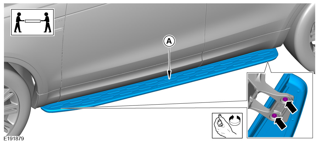
With the aid of another person, install the side step boards (A) and (B).

11

Tighten both the rear side step mounting bracket fixings. Torque: 48Nm

12

Tighten both the front Side Step mounting bracket fixings. Torque: 48Nm

13

Remove the side steps.

14
NOTE
  • Repeat this step for the other side.

Install the trim. Torque: 8Nm

15

Install rear rocker panel moulding.

  • Log into TOPIX and enter your 17 character 'Vehicle Identification Number' and navigate to 'Workshop Manual' section '501-08 Exterior Trim and Ornamentation'.
16
NOTE
  • Hand tighten only at this stage.

With the aid of another person, install the side step boards (A) and (B).

17
CAUTION
  • Do not over tighten the Side Step bolts.

Tighten the side step mounting fixings. Torque: 9Nm

18

Inspect the alignment of the side steps against the body trim.
© Land Rover 2016