SELECT YOUR LANGUAGE
Open upper and lower tailgates.
Remove parcel shelf. For vehicles with power parcel shelf please refer to Owner's Handbook.
The cargo barrier is compatible with the quilted loadspace liner. If you already have a quilted loadspace liner installed or plan to install one later please see the below options. If not then proceed to step 8.
Release the elastic velcro straps around the head rests.
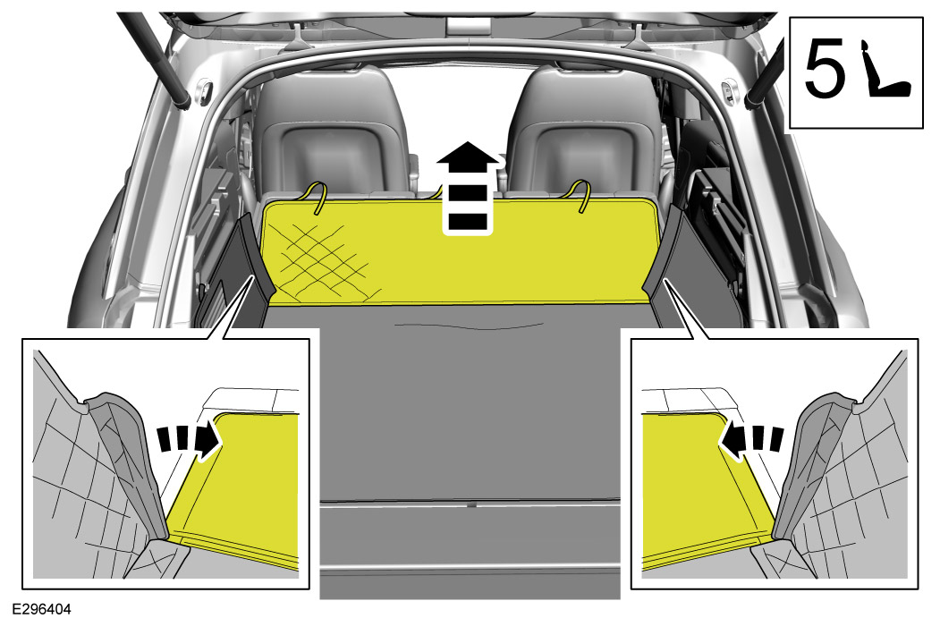
Fold down the second row seats (Please refer to Owner's Handbook if unsure how to do this). Then detach the seat back panel of the quilted loadspace liner from the yellow tabs, so the back panel will then lie on top of the folded down seats.
Move aside quilted loadspace liner tabs to reveal the vehicles D-loops. These will need to be visible for the installation of the cargo barrier.
Fold down third row seats (if present). Please refer to Owner's Handbook if unsure how to do this.
Fold down second row seats. Please refer to Owner's Handbook if unsure how to do this.
Remove left and right trim covers without damage using a plastic trim removal tool.
Install x2 upper pins (D) to cargo barrier with washers (D3), (D2) and nut (D1).
Install side plates (B) with fixings (B1). Torque: 10Nm
Insert cargo barrier (A).
Insert cargo barrier upper pins into headliner fixing points.
Drop the access door and make sure the access door has equal clearance on either side by adjusting the slot on upper mounts.
Adjust the cargo barrier by sliding the cargo barrier left or right on the upper pins. Then close access door.
After aligning the barrier to have same clearance on both side of trims, x2 upper mount pin nuts (D1) are tighten on both sides. Torque: 24Nm
Install domed plastic caps (D4).
Locate D-loops and open.
Install the J-hooks (C).
Install and tighten thumb screws (C1).
Install flexi caps (C2) to the ends of the J-hooks.
When you have the cargo barrier installed you will need to re-attach the seat back panel to the quilted loadspace liner. To do this will be a reversal of steps 6 or 5 and step 4.
Fold up second row seats if you haven't already done so.
Install parcel shelf. For vehicles with power parcel shelf please refer to Owner's Handbook.
Close upper and lower tailgates.
Barrier should be loosened at both the J-hooks. Check the position on roof brackets and retighten J-hooks for every 300 miles or 500 km.
Removal is the reverse of installation. Step 5-8 are only required for initial installation to the vehicle or if moving the barrier between vehicles.